Ansys_logo_(2019).svg


Ansys Design Analysis


DOWNLOAD PDF

Ansys SpaceClaim for Excavator Design

An excavator design for the lunar rover prototype was created using Ansys SpaceClaim, a 3-D computer-aided design software. 

Once the excavator design was finalized, Ansys extracted metrics such as the volume and area of the excavator claw. The Figure below is a picture of an excavator design and its corresponding volume.


Screenshot 2023-10-06 095103


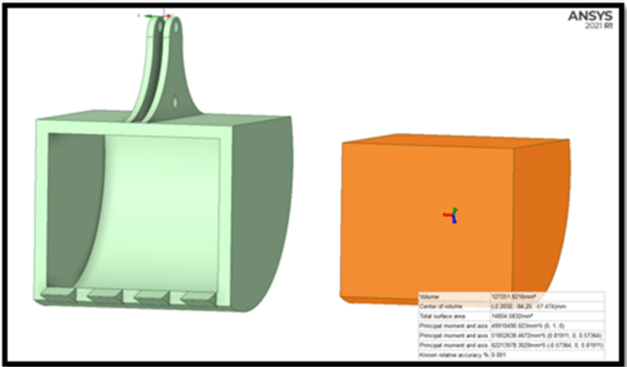
Ansys SpaceClaim supported the lunar rover project by providing data for calculations to determine the excavator's maximum load capacity.

Excavator Maximum Load Capacity

While designing the excavator, the main concern was the maximum load mass the excavator could support during excavation. This maximum capacity was calculated by modifying the density formula, equation 1 below, and resulted in the Excavator Max Capacity Equation, equation 2 below:

     1.  d = M / V
     2. M = d * V

When:

M = Maximum Mass of Excavator Load Capacity
d = Density of the lunar regolith, 1790 kg/m3
V = Volume of the Excavator Claw, 1.27 x 10⁻⁴ m3

The density of the regolith was adopted from the NASA Break the Ice Challenge Rules. The volume of the excavator claw was found by analyzing the design Ansys SpaceClaim, as mentioned previously.

Using this equation, the maximum load mass of the excavator was calculated to be 0.22799 kg. This is the mass the excavator claw can support per each dig of regolith during excavation. 

In later calculations, the maximum load capacity assisted in evaluating the excavator design. It determined how much pressure the excavator claw can endure during excavation on the lunar surface. 

Ansys Static Structural for Excavator Design

Once the excavator design was finalized in Ansys SpaceClaim, the durability of the excavator was analyzed. In Ansys Static Structural, the materials and their properties were added to the excavator design from SpaceClaim. 

Ansys Static Structural supported the lunar rover project by providing data for calculations to determine the excavator's maximum pressure tolerance given different load capacities. Varying load capacities were found using the load capacity equation and calculation mentioned previously. 

Material Selection

An aluminum alloy material was applied to the excavator design using Ansys Static Structural. Aluminum alloy was selected because it is the most common material used on past lunar rover systems. 

Aluminum properties consist of: 

  • Young Modulus of Aluminum Alloy: 71000 Pa
  • Poisson's Ratio of Aluminum Alloy: 0.33

These values are user preferences and can always be modified. 

Load Capacity Scenarios

Since the excavator claw will not always be at maximum capacity, varying load capacities were considered and used during pressure calculations. An optimistic load capacity was 80% of the maximum load capacity, and a pessimistic load capacity was 60% of the maximum load capacity. 

Using the max load capacity mass of 0.228 kilograms, mentioned in the previous calculations, the following varied load capacities are:

  • 80% Load Capacity = 0.1824 kilograms
  • 60% Load Capacity = 0.1368 kilograms

Pressure Tolerance Equation

The lunar surface has an atmospheric pressure of 2.28x10^-12 torr, similar to a hard vacuum. Since this pressure cannot be replicated here on Earth, Ansys tools were used to evaluate the excavator design in the correct environmental conditions. 

To find the excavator's pressure tolerance, the Pressure Equation was used:

  • P = M * g * A
    • M = Maximum Mass of Excavator Load Capacity
    • g = Gravity of the Moon, 1.62 m/s2
    • A = Area of Excavator, 0.014862 m2

Pressure-Given Load Capacity

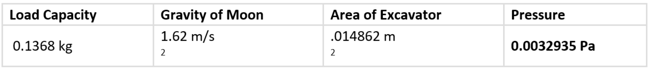
The Pressure Equation was used with each load capacity, 80% and 60%, to calculate the tolerance of pressure that can be exerted on the excavator design.

Screenshot 2023-10-05 140704

80% Load Capacity


Screenshot 2023-10-05 140816

60% Load Capacity

The pressure exerted on the excavator design at 80% load capacity was calculated to be 4.3 MPa. The pressure exerted on the excavator design at 60% load capacity was calculated to be 3.2 MPa. 

Pressure Impact Specifications

After the pressure values were found, they were inputted in Ansys Static Structural to further analyze the excavator design. A fixed support point was needed to identify where the excavator claw would be attached to the robotic arm. Fix support defines correct boundary conditions as in the physical model.  The purple shaded area in the Ansys Static Structural drawing below highlights this support poin

Screenshot 2023-10-05 141250

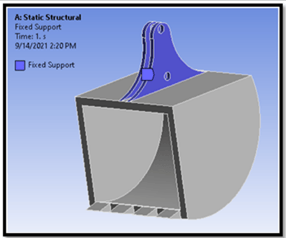
Fix Support Point of Excavator Claw

A pressure area was also defined in Ansys as the bucket area of the excavator claw. This is where the excavator design will take on the most pressure. The red-shaded area in the Ansys drawing below highlights this area. The direction of the pressure is expressed as the black area on the red area. The amount of pressure exerted was also recorded in Ansys.

Screenshot 2023-10-05 141704

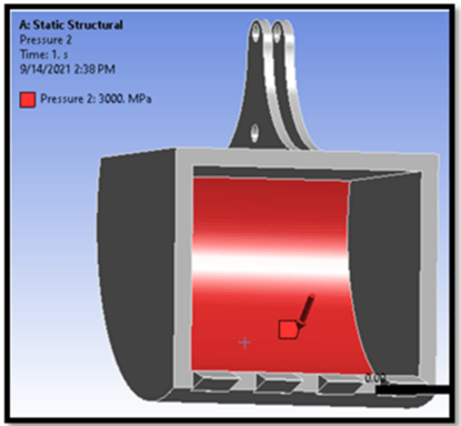
Pressure Area of Excavator

Pressure-Given Load Capacity

Some concerns considered before the final evaluation of the excavator began were:

  • Normal Stress
  • Elastic Strain
  • Deformation

Normal stress is a force that acts perpendicular to the surface of an object. In the excavator design, this was the digging motion and loading of regolith on the excavator claw during each excavation. Stress continues to build as the excavator continues filling the bucket area. 

Elastic Strain is caused by forces that are parallel to and lie in planes or cross-sectional areas. In the excavator design, this occurred when the excavator was holding and maneuvering a load of excavated regolith from the excavator claw to be dumped in the lunar rover's storage unit. 

Deformation is the physical transformation of an object brought by forces like gravity, mass, and temperature. In the excavator design, this will occur depending on the duration of the mission. Using Ansys analysis determined the regions where deformation will occur.

Pressure-Given Load Capacity

Once Ansys Static Structural had all the needed data inputs, the final analysis of the excavator was performed.

Prototype Excavator Filled with 80% Regolith

Screenshot 2023-10-05 142140

Excavator Deformation with 80% Capacity Animation


Screenshot 2023-10-05 142307

Excavator Strain with 80% Capacity Animation


Screenshot 2023-10-05 142414

Excavator Stress with 80% Capacity Animation


Prototype Excavator Filled with 60% Regolith

Screenshot 2023-10-05 142603

Excavator Deformation with 60% Capacity Animation


Screenshot 2023-10-05 142659

Excavator Strain with 60% Capacity Animation


Screenshot 2023-10-05 142754

Excavator Stress with 60% Capacity Animation

Fatigue Analysis vs. Excavation Cycle

The results show the structural analysis of the excavator design. Evaluating the structural analysis is to determine the strength and stability of the design under actual loading conditions. Some of the analysis that was considered are the following:

  • Strain
  • Stress
  • Deformation

These strain, stress, and deformation will lead to fatigue in the excavator claw. Fatigue was determined by calculating each excavation cycle. An excavation cycle is the excavator digging up regolith. The most pressure will be endured during the excavation and repetitive cycles will lead to failure of the excavator. The fatigue analysis determines that the max strain, stress, and deformation will occur after a number of cycles. This cycle for the according load capacity follows:

Screenshot 2023-10-05 143146

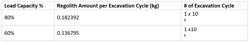
Knowing the failure of the excavation cycle could lead to a preferred maintenance schedule and plan. This will also assist in determining more accurate results when simulating the rover's excavation mission.

Ansys & Innoslate for Lunar Rover Mission Engineering

The success of the lunar rover mission depends on the quality of mission engineering, which includes planning and testing of subsystems to ensure optimal functionality in the lunar environment. Thorough testing and evaluation of the excavation subsystem is critical due to the lack of maintenance support on the moon. To achieve this, engineers use Ansys simulation software to test the subsystem's functionality in the appropriate environment, providing valuable data on its performance and reliability. Innoslate, a mission engineering software tool, uses Ansys data as input to further optimize the excavation subsystem and guarantee the mission's success. This section will detail how Ansys provides data for mission engineering and Innoslate's use of this data for optimizing the excavation process.

Scaling the Rover for the Mission

The Ansys simulation focused on the rover prototype, but for mission engineering, it had to be scaled to the actual rover size allowed by NASA. The ratio was 1:20 between the prototype and full-scale rover, providing more accurate results for mission engineering. To simulate the mission engineering it had to rely heavily on Innoslate's discrete simulator. 

The Excavation Subsystem

In the context of the lunar rover mission, the excavation subsystem is responsible for collecting lunar regolith from the moon's surface. However, the process of collecting regolith comes with its own set of challenges, including the risk of damage to the excavator claw, which cannot be repaired and comprise the mission.
 
A diagram and simulation were created to highlight the excavation process of the lunar rover. To mitigate risk, the process was divided into two cycles: Excavation Cycle & Maintenance Cycle. This can be seen in the diagram below.

Screenshot 2023-10-05 143747

The excavation cycle focuses on the design and load capacity of the excavator claw and the rover storage bed, ensuring that the claw can collect a certain amount of regolith without exceeding the maximum load capacity of the rover's bed. This is important because the rover's bed can only transport a certain amount of regolith back to NASA's Regolith Water Plant for further processing.

The maintenance cycle takes into consideration the pressure tolerance of the excavator claw and how it can withstand damage during the excavation process. If the excavator claw gets damaged, the maintenance cycle constrains the amount of regolith collection since the claw cannot be repaired on the moon. The maintenance cycle will collect regolith and keep track of the amount until failure. 

Excavation Cycle Analysis

The excavation cycle duration is heavily influenced by two factors:

  • Load Capacity of Excavator Claws
  • Max Capacity of the Rover Trunk Bed


The capacity of both items was determined through Ansys' simulations. Based on the simulation the following was calculated:

Prototype Rover Measurements:

  • Each Excavator Claw: 0.18kg
  • Rover Trunk Bed Max Capacity: 2.5 kg


To scale up from the prototype measurements to full-size rover measurements, a ratio of 1:20 was used. This ratio implies that the load capacity of the full-size rover's excavation claw and rover's trunk bed is 20 times greater than that of the prototype. Therefore the full-size measurement goes as follows:

Full-Size Rover Measurements:

  • Each Excavator Claw: 3.6 kg
  • Rover Trunk Bed Max Capacity: 50 kg


The excavation model assumes that during each excavation cycle, the rover will collect 7.2 kg of regolith using the 'Resource' construct, labeled as "Storage Capacity". The ' Loop' construct, labeled as "Excavation Cycle" provides the condition that the collected regolith does not exceed the maximum capacity of the rover's trunk bed. This means that each iteration of the 'Loop' construct counts the amount of regolith collected and is conditioned not to exceed the maximum rover capacity of 50 kg.  

Maintenance Cycle Analysis

The maintenance cycle for the rover's excavation system was designed, considering the excavator claw's fatigue analysis. The analysis used Ansys simulation to determine the pressure tolerance required for the excavator claw to perform a single excavation cycle. The simulation showed that the excavator claw could withstand up to 1 x 10⁸ cycles of excavation before reaching its limit. 

To prevent the excavation system from failing due to the excavator claw reaching its limit, a condition was added to the 'Loop' construct, labeled as the "Maintenance Cycle". This condition allows the cycle to continuously run through the excavation process before reaching 1 x 10⁸ cycles, the limit of the excavator claw. The 'Resource' construct was used to track the amount of regolith being collected, labeled as "Regolith Collect", and the number of excavation cycles performed, labeled as "Excavation Cycle".

Using the 'Loop' and the 'Resource' constructs, the Innoslate model can determine whether the rover can collect the required regolith for the mission before the excavation system needs maintenance or fails. This allows for effective planning and maximizing the rover's productivity.