
.svg) Steven Dam
Steven Dam
Leading the Digital Transformation With Innoslate
Not up for the read? Sit back, relax, and watch the webinar recording! Organizations today are increasingly recognizing the need for digital...
.svg)
Recently, a senior US Air Force leader gave a presentation with the slide in Figure 1 showing the challenge areas for continued innovation in Digital Engineering.
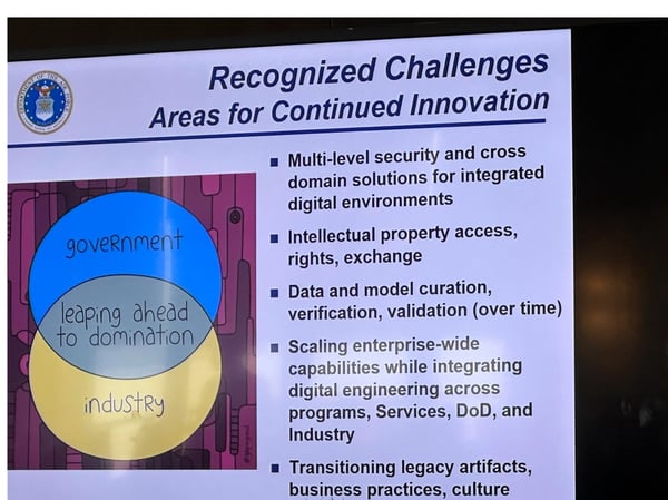
Figure 1. USAF Challenges for Digital Engineering
These challenges have existed for a long time. Most current/legacy tools have no means to support multi-level security/intellectual property security as they are not real-time collaborative tools to begin with. We propose a series of solutions to all these challenges based on SPEC Innovations’ Innoslate tool.
Innoslate is currently hosted at the NIPRNET and SIPRNET levels on the Air Force Systems Engineering Resource Center (AFSERC), so it is approved by the USAF. The tool is also used for systems engineering instruction at the US Air Force Academy, Air Force Institute of Technology (AFIT), and the US Naval Postgraduate School. Innoslate is also available on JWICS and IC-ITE. Innoslate has been containerized and installed on Iron Bank. Innoslate also has a STIG from DISA. So, hosting Innoslate on FENCES, as proposed below, should be fairly easy and quick.
Innoslate® was designed and developed as a cloud-native, collaborative systems engineering and program management tool. The lead architect for this tool worked at Los Alamos National Laboratory (LANL) in the late 1970s and early 1980s on distributed computing projects. Multi-level security was a goal even then, but there was no easy means to achieve that goal.
Originally Innoslate versions 1, 2, and 3 focused on collaboration and built a real-time collaborative environment that could be used by people worldwide. However, the idea of data hiding was also of interest to the user base for Innoslate. So for version 4.0, Innoslate was rearchitected to provide a security sandbox we call an Innoslate Organization. Within an Organization, individual projects can be created. The owners of these projects determine who has access to the project. Except for Organization Administrators, only the owner and those they shared the project with would even know of the projects’ existence.
Now, if one project owner had wanted to put some of the information in Project A so to have that information in context with another project (Project B) they had access to, then they would use “cross-project relationships” to put that information into Project B from Project A.
Figure 2 shows a notional example of such a project (Project A – p/5121). This entity has been linked to another project (Project B – p/1950) as seen in Figure 3. Note project IDs can be seen as part of the URL for the webpage.
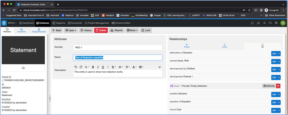
Figure 2. An entity in Project A that will be shared in Project B
The screenshot shown in Figure 3 is how the user who is the owner of Project A would see the information in Project B.
However, other users of Project B that do not have access to Project A see the picture in Figure 4. These redaction bars show up in any view where the information is used, including diagrams.
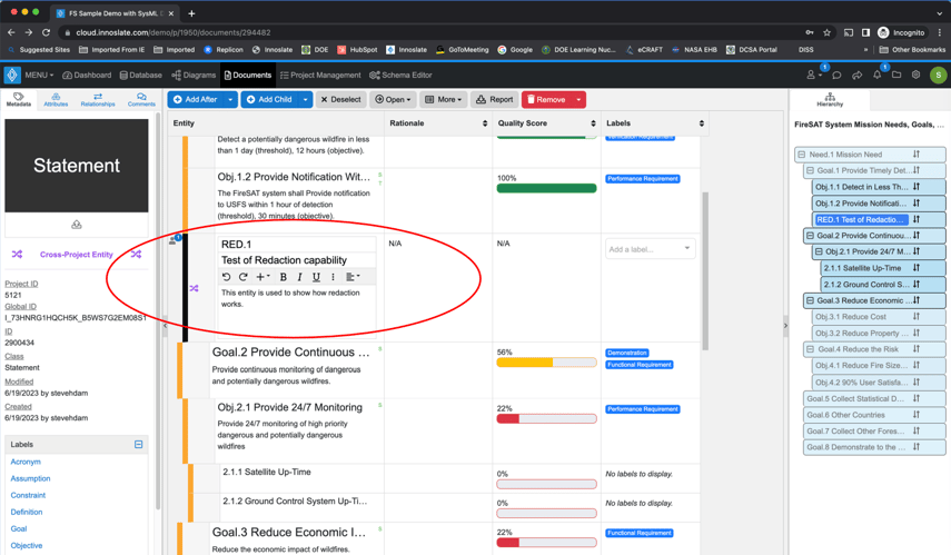
Figure 3. Entity from Project A shown in a Project B document as viewed by the user with access to both projects
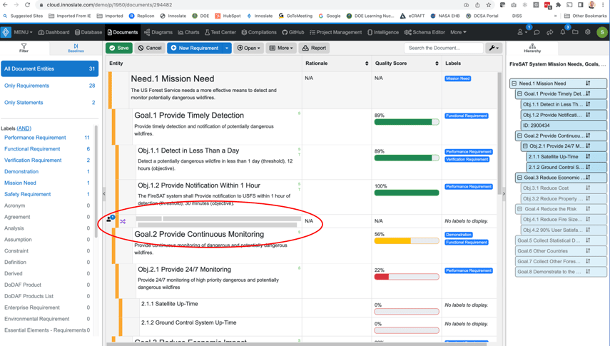
Figure 4. Project B from the perspective of a user who does not have access to Project A
So the question is how does this aid in solving the multi-level security problem? The answer is Innoslate could act as the bridge between the classification levels. For example, if Project B was unclassified and Project A was classified SECRET, then users with a .smil account could be provided access to both projects, and users with a .mil account would have access only to Project B. Clearly for this to work, Innoslate would have to be hosted in a classified cloud that supports multi-level security. Such as cloud exists: FENCES. We propose an experiment where Innoslate is hosted on FENCES and projects are created for access at least two different security levels. We would begin with unclassified information in all projects until security experts review this capability. If problems are found, SPEC Innovations can modify Innoslate to enhance this feature. Lessons learned from this experiment could be applied to other applications, not just Innoslate.
Clearly, this method would also work for intellectual property. The Government would have a common project, such as B, and information from one contractor would be represented in Project A. Another contractor that had access to Project B, but not Project A, would only see the redaction bars shown in Figure 4.
This challenge could be addressed on AFSERC today. Simply set up two contractors with their own projects and have a third Government project within a government-controlled Innoslate® Organization. The Government would have access to all three projects, but the contractors would have access only to their project and the common one.
In addition, each contractor could have other projects that contain IP that they don’t want to share with the Government. Those projects could be hosted on contractor facilities. If they wanted to share a document from their internal project with the Government, they would export that document (digital artifact) to an XML file and then import that document into their project on the Government system. Other contractors would not have access to the new document. Innoslate® provides a means to update XML between projects, as long as the same global IDs are used.
This approach could be tested as well along with the multi-level security test discussed above.
Innoslate can also support data and model curation. For users of Innoslate, it provides a “Manage Projects” view that enables users to put projects in “folders,” sort, filter, and search for projects. Figure 5 shows the Manage Projects view from Innoslate.
Within Innoslate projects, an entry into each entity’s history file is created for any changes. Documents can be baselined to capture versions of these digital artifacts. Test Suites also record test cycles to show how results change from each execution of a test.
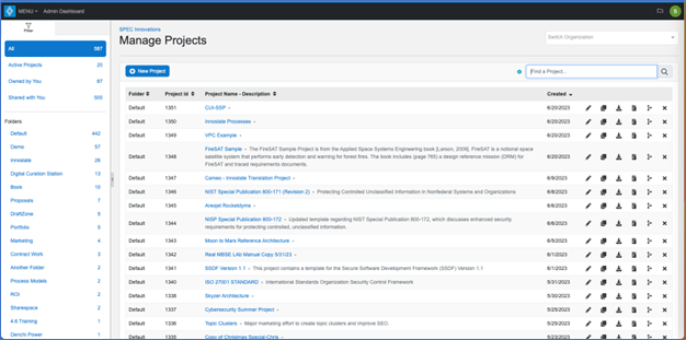
Figure 5. Innoslate's Manage Projects View provides the means to organize and curate projects
For data and information from other tools, Innoslate’s database has an “Artifact” class that enables users to upload files of any type for curation. The description field is used to capture metadata about the files to enable future users to know what information they are downloading. Figure 6 shows an example of a CAD file upload. In the case of CAD files, Innoslate has a CAD viewer to show systems engineers the results of the mechanical engineering work. Figure 7 shows the results of selecting the black “View CAD” button.
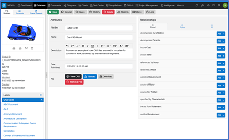
Figure 6. Curation of files from other tools is an important feature of Innoslate
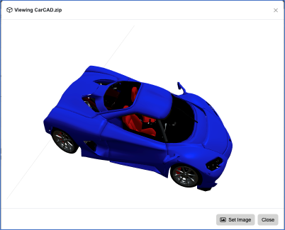
Figure 7. The combination of a .obj and .mtl CAD file provides a detailed model of the car
For verification and validation of models, we can translate the models from other tools and execute them with Innoslate’s built-in simulators (discrete event and Monte Carlo). In addition, Innoslate’s Test Center provides a means to capture all the V&V activities, including results from other digital engineering tools. Recently, the Innoslate developers were able to create interoperability with Selenium for V&V of software. Other users have interfaced with LabView™.
Innoslate was designed for scalability. The choice of developing a cloud-native application came from the requirement by the NASA Chief Engineer in 2010 that systems engineering tools needed to be scalable to deal with millions of objects. Innoslate has been tested on 10 million objects and 500 simultaneous users.
Although this level of scalability might support a single Command, providing scalability across the entire enterprise will require a data mesh technology infusion. Recently, SPEC Innovations, along with By Light Corporation, Oracle, and ProcessUs, responded to an RFI from the US Army ASA(ALT) Data, Engineering, and Software (DES) organization, which also presented at the same conference just after the Air Force presentation above. In this paper, the team proposed a solution that would combine Innoslate, data mesh technology (Oracle Corporation), unsupervised AI/ML (By Light), and knowledge graphs (ProcessUs Group) to achieve the Army’s vision of a Unified Data Reference Architecture. This capability would enable controlled access to any web-based tools and data, as well as the data governance necessary to maintain high levels of security.
To take advantage of the technologies discussed above, the USAF must move beyond desktop tool technology and move into the cloud-native world fully. Change takes time (days to months). Organizational change takes years.
Part of the difficulty being encountered by the DoD and other organizations in creating a complete digital enterprise comes from the fact that many of the tools and techniques developed in the 1990s and in common use today, are difficult to learn and unnecessarily complicated. People don’t have the time and energy to become experts in specific tools and languages.
We, digital systems engineers, need to realize that other engineering disciplines, such as software, mechanical, electrical, etc. have advanced digital tools of their own. What’s been missing is a way to translate and curate the detailed design engineering data, transforming it into information that decision-makers and other members of the organization can understand and make good decisions with. Systems engineers are critical to this translation of data into information. Systems engineers have attempted to apply the Systems Modeling Language (SysML) to meet this need, with some limited success. This limited success is not scalable to the entire enterprise. Organizations, such as NAVAIR, have attempted this and found that many people in other disciplines are overwhelmed by the complexity of the language and the lack of relevance to their jobs.
Currently, to understand a complex language like SysML, personnel have had to take weeks of training just to get started. The SysML syntax is complicated and confusing to many people. The language is based on a set of software-centric diagrams (Unified Modeling Language) with a few “extensions” for systems engineering, in particular the Requirements and Parametric Diagrams. The Requirements Diagram cannot scale to the tens of thousands of requirements needed for any real-world system. The Parametric Diagram is a means to diagram equations. Since almost everyone has an education in Mathematics and every technical person has taken higher level Math courses, the elegant and easy-to-understand equations are transformed into a diagram form, which has some utility, but is very limited again as a means to express complex thought clearly.
Given these facts about the language and the lack of tool interoperability, which SysML v2 may help some, but will not be the panacea senior managers are hoping for, we need another way to translate and communicate design engineering information to the decision-makers. What are decision-makers mostly interested in? Cost, Schedule, Performance, and Risk. Almost everything of interest to them fits into these four classes of information. It’s not the system they care about, it’s how the system performs, how much it costs, whether it will be there when needed, and how risky is this investment. Those are a decision maker’s interrogatives.
So as we stand at a transition point from SysML v1 to the next language, it may be worth considering a language that would be much easier to learn and use by everyone in the organization. That language is the Lifecycle Modeling Language (LML). LML is an open standard managed by the Lifecycle Modeling Organization (LMO – www.lifecyclemodeling.org). LML provides a relatively simple semantic ontology that includes classes (nouns), relationships between the classes (verbs), attributes of the classes (adjectives), and attributes of the relationships (adverbs). It also specifies three diagram types as mandatory but embraces the use of any diagram type to ensure all the views users need are available. Figure 8 provides an overview of the language.
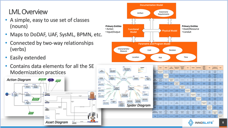
Figure 8. LML provides an easy-to-learn language for digital engineering
LML is currently taught in all the Service Academies (USAFA, USAMA, USNA, NPS, AFIT) as well as in hundreds of universities around the world.
Figure 9 shows the difference between what it takes to understand LML vs. SysML.
Figure 9. A simple book on LML demonstrates the difference in try to understand SysML
A good example that shows how accessible LML really is, comes from the Business Organization at Naval Surface Warfare Center Carderock Division. They we able to learn LML and how to model their processes in a matter of a few weeks and used that capability to identify and suggest business process changes to save the organization and the Navy hundreds of thousands of dollars by improving the travel process. None of the Business organization personnel were systems engineers.
To transition from current SysML to LML is fairly easy, as the LML specification version 1.1, released in 2015, provided an ontology for SysML. Innoslate implements LML and provides all the nine SysML diagram types, along with the LML and other diagrams. All these diagrams share the same information, they just have different ways to portray them. Figure 10 shows a SysML Action Diagram and an LML Action Diagram. Using Innoslate, a change in one is automatically included in the other.
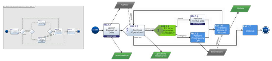
Figure 10. LML transforms the more difficult-to-read SysML diagram into a clear, easy-to-understand flowchart with explicit inputs and outputs
Currently, the LML Steering Committee is working on mapping SysML v2 to LML, a much more difficult task as it is much more complex than SysML v1.6.
Another problem with SysML v2.0 is that the focus appears to be the creation of a new “programming language.” What the authors of v2.0 do not seem to realize is that most systems engineers are not adept at programming to begin with. The purpose of the models has been to abstract from a coding language the essence of the system. Other non-engineering stakeholders have even less understanding or interest in learning a new programming language.
For this reason and the many reasons above, it becomes clear that if the Air Force wants to gain acceptance for “digital transformation” across the entire enterprise, they need to accept that a new language and tool set is needed to support the systems engineering portion of the lifecycle. We believe LML is that language.

Not up for the read? Sit back, relax, and watch the webinar recording! Organizations today are increasingly recognizing the need for digital...
Don't feel like reading? Watch the recording!

An unfortunate fact of life is that it can sometimes be complicated - and for many engineers, so are today's modern systems. What makes these modern...