

.svg) SPEC Innovations Team
SPEC Innovations Team
Rethinking Requirements Derivation: Part 2
By John Fitch, for Project Performance International (PPI) [Fitch, John. “Rethinking Requirements Derivation: Part 2.” PPI Systems Engineering...

By John Fitch, for Project Performance International (PPI) [Fitch, John. “Rethinking Requirements Derivation: Part 1.” PPI Systems Engineering Newsjournal (SyEN), no. 129, October 2023, pp. 18-27.]
Three prior articles in PPI SyEN have laid the foundation for this topic.
In the article Introduction to Decision Patterns in PPI SyEN Edition #107 (December 2021), a decision was defined as a “fundamental question or issue that demands an answer or solution,” the Decision class (of information) was distinguished from the Alternative class, and the concept of decision-to-requirements derivation traceability was introduced.
In the article, Decision Patterns – So What? in PPI SyEN Edition #111 (April 2022), a decision-centric information architecture (metamodel) was elaborated that explained the conceptual basis behind decision-to-requirements derivation traceability. Derived requirements were stated to be the inherent consequences that flow from the definition of the solution alternative that has been chosen in an “upstream” decision. In other words, “all requirements are derived requirements” and “decisions create requirements.”
In the article, Reverse Engineering Stakeholder Decisions from Their Requirements in PPI SyEN Edition #113 (June 2022), decision-to-requirements traceability was presented as the basis for the ability to reverse engineer stakeholder choices and to validate and refine a set of stakeholder requirements. A requirements derivation heuristic was introduced in the form of a question to be applied to each “upstream” decision:
“How does the chosen alternative’s Structure, Behavior, Footprint, Interfaces and Lifecycle impose constraints on the rest of the system?”
In the second article, four assertions were stated as “givens” based on the author’s
experience with capturing decision-to-requirements traceability across 150+ customer projects:
Readers are encouraged to take a quick read through these prior articles to gain a fresh grasp of these foundational ideas.
This article will explore in more detail how different types of requirements may be derived from a pattern of six decisions that must be made when defining how system-level functions will be delivered by a solution design. This six-decision pattern within the broader system/product design decision pattern forms a reusable solution design kernel that may be applied to elaborate the physical and functional design of any system.
Part 1 of this topic will summarize the theory and principles behind decision-centric requirements derivation using the six-decision pattern. Part 2 (to be published in a subsequent edition of PPI SyEN) will provide a working example of the theory in practice.
The System/Product Design decision pattern was the first pattern developed by the author and has been the most frequently used pattern across multiple industries and domains. [1], [2] The full pattern has ~100 decisions.
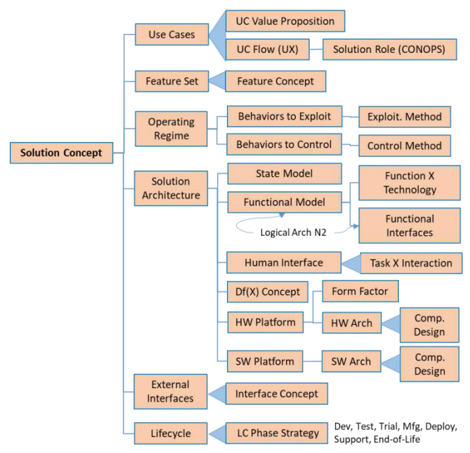
Figure 1: Generalized Top-Level System/Product Design Decision Pattern
Experience in using decision patterns across a wide variety of projects has taught the author the importance of flexibility; the pattern should not be applied rigidly with every branch and node captured with the same rigor or level of detail. In some cases, a “flat” Top Five or Top Ten Decisions List is sufficient to guide the decision-making on a project. In other cases, a fifty or one-hundred-decision hierarchical model is called for based on the problem at hand, e.g., a mission-critical system with high novelty and technical complexity. Refactoring the model is also a common occurrence; decisions may be merged or split depending on the nature of the problem being addressed and judgments as to where more or less detail will reduce complexity and improve decision quality and decision analysis efficiency.
The six-decision pattern described below is an example of such refactoring to match the need to provide a reusable design kernel that illustrates the typical decision-to-requirement-to-decision interactions between the design choices.
Few products deliver a single system-level function or lend themselves to mirroring in which the physical decomposition (Component 1-N) of the solution precisely matches the functional decomposition (Function 1-N) of the problem.
Complete alignment is needed between the physical and functional models; the functional model is always the logical representation of the physical solution concept. If the functional and physical models are not aligned, one or both of them are wrong.
Engineering would be simpler if we could represent all the thinking that it takes to transform a problem definition into a full solution as a single decision for each branch of the system
decomposition. However, this is impractical. That single decision would have too many criteria (hundreds?) and alternatives (thousands?) to consider in a single decision analysis. Whether using a formal decision pattern or done in an ad hoc fashion, design is generally broken down into a manageable set of decisions. The advantage of a pattern is the ability to reuse lessons learned during previous designs and reduce the cognitive effort needed on the current project.
Table 1 summarizes the six decisions that will be made (preferably as a result of explicit analysis) during the design of an implementable physical solution to virtually any problem. Note that this is a decision pattern; there may be multiple instances of these decisions made during a design project.
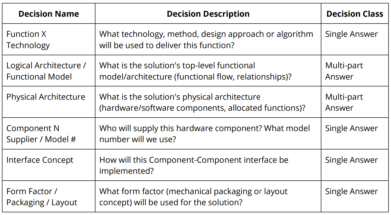
Table 1: Decision Pattern – Design Kernel
Products and systems are typically part of a larger portfolio of solutions. Each product fills a niche in that portfolio based on its value proposition relative to other offerings. Given that role (the essence of the product concept), system-level functions are derived from the use case, feature set, external interface, and lifecycle decisions that “scope” the product. [3] Each system-level function (those that have been allocated to the system of interest within an approved use case) will require a decision that addresses how the function will be delivered by the system of interest. Typically this decision is expressed as a “How?” choice between technologies (in the case of most hardware systems), methods (in the case of
process design), algorithms (in the case of software) or overall solution design approaches.
External interface decisions “bound” the functionality of the system of interest by specifying the inputs that the system has to be able to process and the outputs that the system has to be able to generate to interact as desired (by the stakeholders) with the outside world.
Lifecycle decisions “birth” new system functions that support system functional interactions with enabling systems such as testing, manufacturing, deployment, support, and end-of-life.
As shown in Figure 2, these product-scoping decisions set the context for using the solution design kernel recursively down the system breakdown structure one “branch” at a time. Used first at the system level to define next-level system elements, the pattern may then be reapplied for the design of each system element until no more design effort is required, i.e., when off-the-shelf (OTS) components or non-developmental items (NDI) are all that is needed to describe a buildable solution.
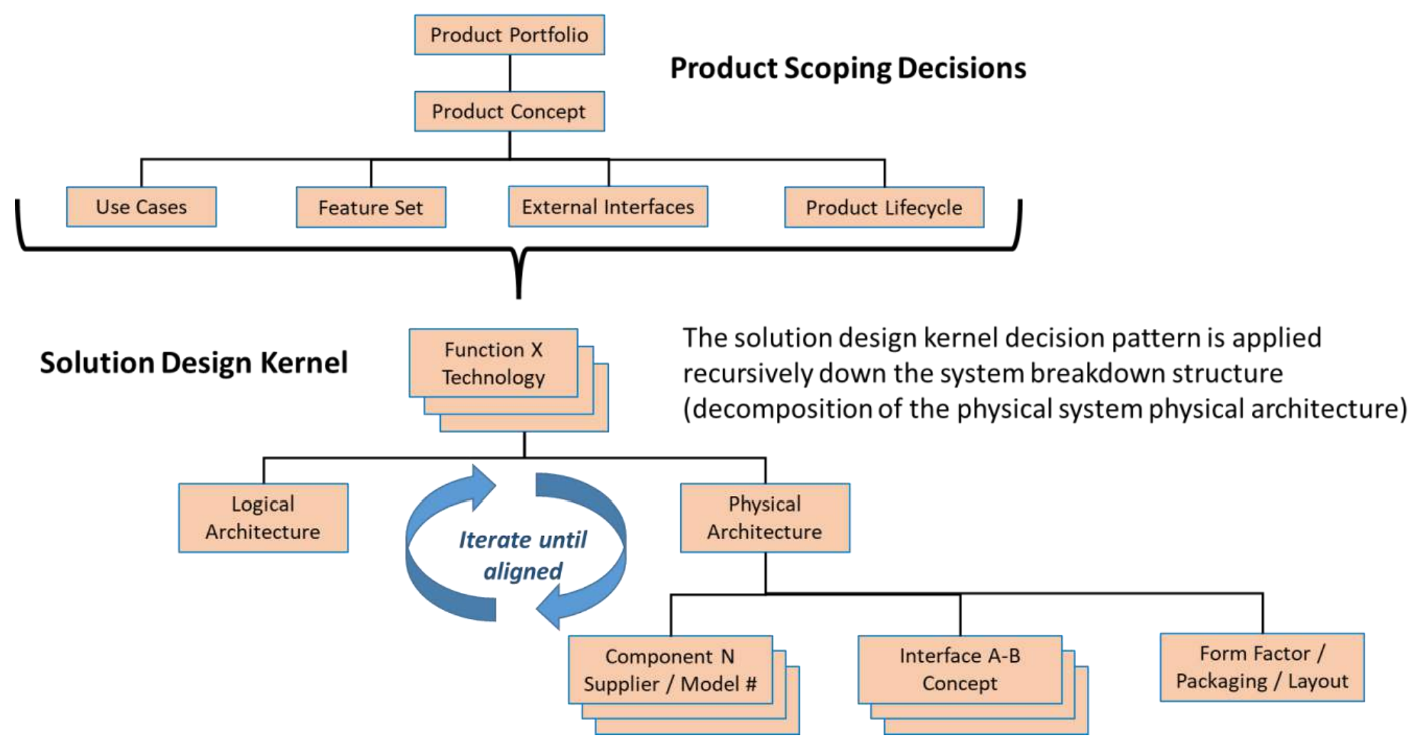
Figure 2: Product Scoping Decisions Set the Context for Recursive Use of the Solution Design Pattern Kernel
Multiple functions may be addressed in a single decision analysis (Choose Technologies for Functions X, Y & Z), but every system-assigned function must be covered in at least one such decision. “How” must be decided; it is better if that is done through an explicit decision-making process rather than being buried within a system architectural model that lacks recorded rationale that can be revisited if/when things change.
The Function X Technology decision expects a single answer (one alternative, committed for
implementation; down-selected from all other options) except in cases where functional redundancy is demanded.
As shown in Figure 3, the Function X Technology decision is the primary source of derived functional requirements (FRs) and associated performance requirements (Measures of Performance – MOPs) on the next-level system elements. As such, each such decision drives the decomposition of the system functions into solution-level functions and also drives the mathematical relationships (flowdown) between system-level MOPs and solution-level MOPs.
It is important to remember that decisions create requirements based on the alternative chosen. When using decision patterns, a decision is a fundamental question or issue that demands an answer or solution. It is the alternative that emerges as the winner from the decision analysis process that has inherent consequences based on the alternative’s structure, behavior, footprint, interfaces, and lifecycle.
Consequences that were “attached” to not-chosen alternatives are moot as soon as the decision is made unless the chosen alternative doesn’t “pan out” and the decision has to be revisited.
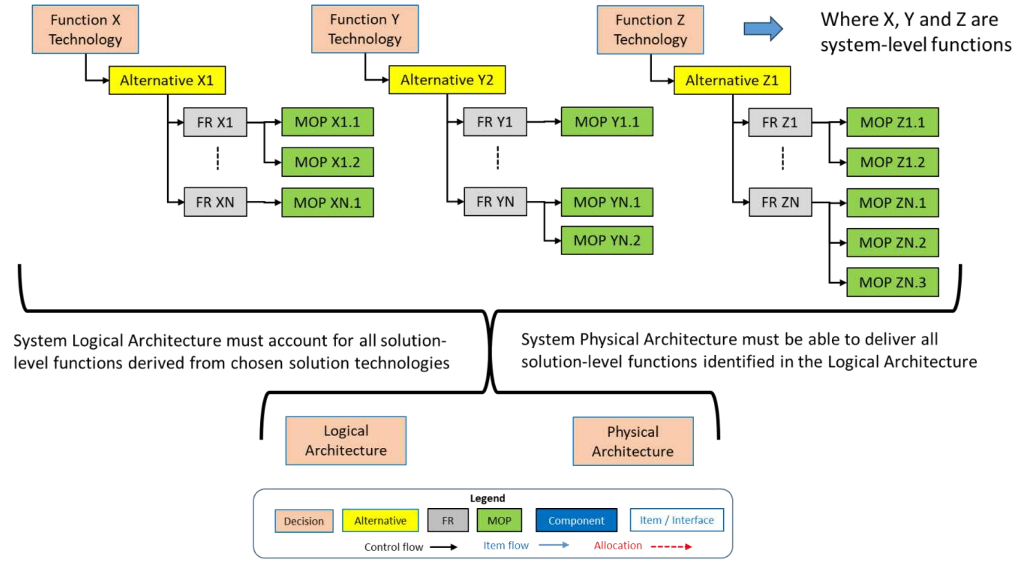
Figure 3: Requirements Derivation from Technology Decisions
The Function X Technology decision may drive the functional decomposition and performance flowdown, but it doesn’t typically populate and resolve all aspects of the solution-level functional model. A technology or method may be implemented in multiple ways, each of which might yield variants in control flow (sequencing of functions), item flow (of information, material, or energy between functions), or handling of anomalous inputs or system faults.
More significantly, the system’s logical architecture must balance the needs of all system functions. The best technology (and therefore next-level decomposition) for Function X may not mesh well with the best decomposition of Function Y and Function Z, leading to design iteration resolved through a higher-level tradeoff. Such a multi-decision tradeoff is common when combinations of new technologies are being evaluated.
The Logical Architecture / Functional Model decision is a multi-part answer decision for which the best representation of each alternative is some form of functional model (e.g., boxes and arrows). In a very simple case, a functional decomposition hierarchy may suffice, but typically a more comprehensive and notationally rigorous model is needed such as a Functional N-Squared Diagram, Functional Flow Block Diagram (with control and item flow), or Activity Diagram.
The Logical Architecture / Functional Model decision creates behavioral requirements consistent with the previously chosen technologies. These requirements express dependencies between functions and precisely specify functional interactions in terms of inputs/outputs and their characteristics.
The functional and performance requirements derived from the Function X Technology and Logical Architecture / Functional Model decisions must eventually be realized in physical entities, e.g., hardware components, software modules, facilities, human actors, or data stores. The Physical Architecture decision creates:
There is often a high degree of iteration needed between the logical and physical architectures of the system. The functional model, by detailing the behavior needed by the system, helps refine the physical architecture by specifying what has to pass between functions and the characteristics (e.g. bandwidth, geometry, etc.) of the physical interfaces needed to ensure that this item flow delivers what is needed from each allocated function. The specification of the item flow between functions also helps to clarify the definition of each function by making explicit which inputs will be transformed into which outputs when each function is performed.
Figure 4 illustrates this complementary relationship between logical and physical system models. The logical architecture model is shown in the form of a Functional Flow Block Diagram with both control and item flow. The physical architecture model is shown as a Schematic Block Diagram. The red arrows represent the allocation of functional requirements (and associated MOPs, not shown) to the system elements, aka Configuration Items (CIs).
Control flow (functional dependencies) is shown as black arrows. Item flow (e.g., Item A, B, etc.) is shown as blue arrows. If two functions (with item flow between them) have been allocated to two different system elements, there must be a corresponding physical interface (e.g., IF1-2, IF2-3) between those system elements that can “pass” the items.
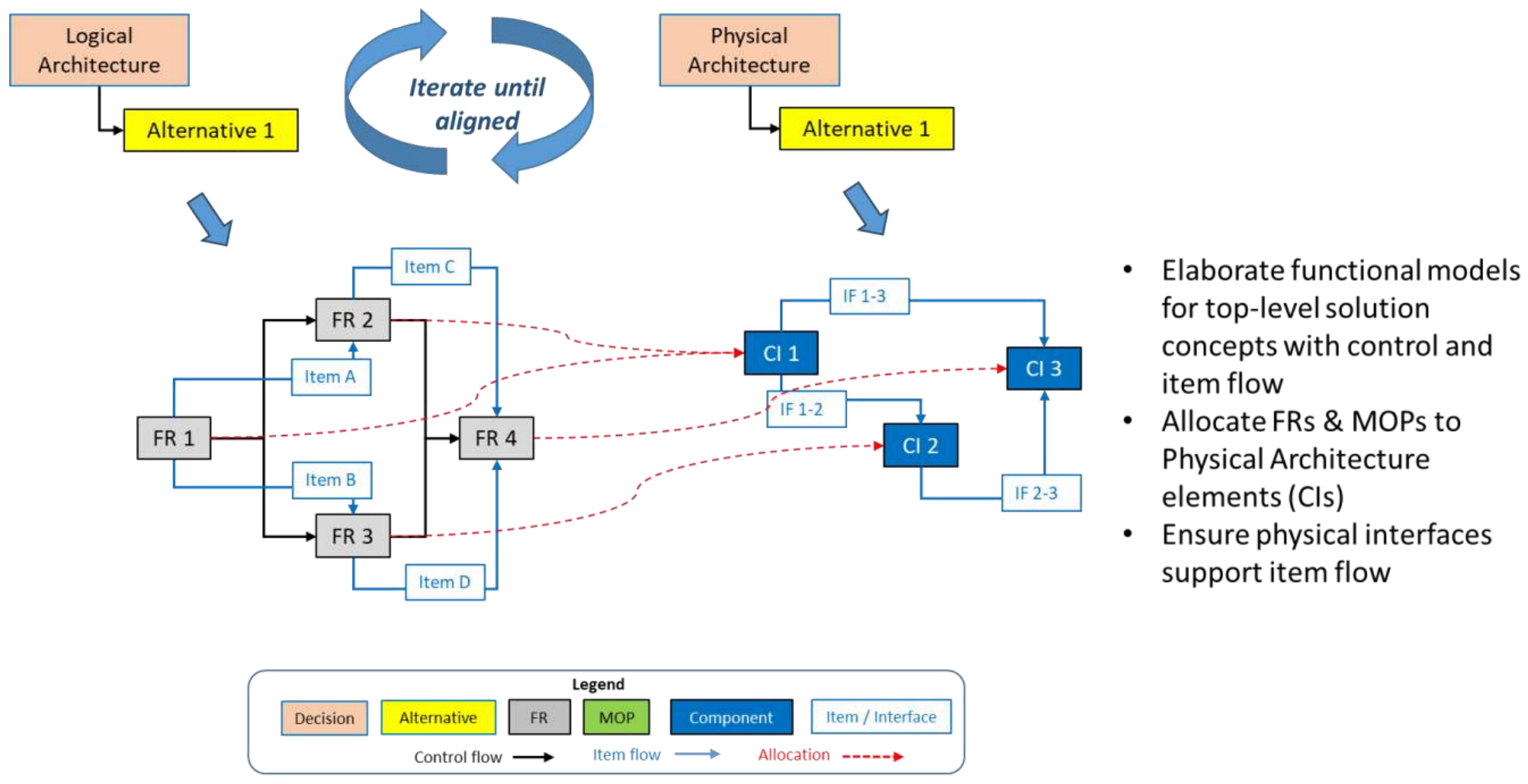
Figure 4: Aligned Logical and Physical Architecture Viewpoints Linked by Allocation
The Physical Architecture decision is a multi-part answer decision for which the best representation of each alternative is some form of architectural model. In a simple case, a system breakdown structure (hierarchy of system elements) may suffice, but typically a more comprehensive and notationally rigorous model is needed such as a physical N-Squared Diagram or Schematic Block Diagram.
The Physical Architecture decision gives birth to all system elements and the interfaces between them. As such, this decision is the point where the physical decomposition of the system into next-level elements occurs, and “existence” requirements are created that define the next-level structure of the solution.
Each system element conceived in the Physical Architecture decision must be “sourced” as either an off-the-shelf (OTS) component or non-developmental item (NDI) or as a developmental item that requires design, and verification & validation effort. If the Physical Architecture decision is committed to an architecture comprised of ten system elements, we would expect ten discrete Component Source/Model # decisions. Each of these decisions, aka Make (by whom)/Buy (from whom) choices, will result in commitment to a particular sourcing strategy. In the case of an OTS/NDI solution, the alternatives are represented by a vendor name, component name, its associated model number, and likely some form of data sheet that describes the characteristics of the component.
The Component Source/Model # decision is a typically single-answer decision unless multiple vendors/sources are sought to mitigate risks to component availability or from vendor turnover.
OTS/NDI solutions create footprint, interface, and lifecycle constraints. These are already-designed solutions that:
If the sourcing decision commits to the use of developmental items, these same characteristics must be captured in the developmental item’s specification so that the impact on overall system constraints (e.g., footprint budgets, interfaces, lifecycle compatibility) may be managed.
As noted above, the Physical Architecture decision gives birth to all the interfaces between system elements. This implies an Interface Concept decision for each physical interface, e.g., CI1-CI2 Interface Concept. The number of these decisions required is entirely dependent on the system's physical architecture and can be “read” quickly from the number of “off-diagonal cells” if the physical architecture is represented by an N-Squared Diagram. In many cases, these decisions lend themselves to common solutions such as a data bus or a common set of OTS physical fasteners.
The appropriate format for defining an interface concept varies widely depending on whether the interface is passing information, energy, or matter.
The Interface Concept decision is a single-answer decision unless interface redundancy is required to meet reliability or failure response requirements.
The interface requirements that are derived from this decision may be documented in an Interface Requirements Specification (IRS) or as an Interface Requirements section with the specification for each system element.
All physical systems have constraints, e.g., external interface and lifecycle, on their overall space claim and many have requirements, e.g., aesthetics, usability, or safety, that influence their layout/shape. The physical configuration of the system elements matters; their layout may influence the ability to achieve performance requirements.
The alternatives chosen in the Component Source / Model # decisions when “added” together define the volume of the system elements that must be arranged in a layout that fits within the physical constraints of the system. Most modern systems suffer from stakeholders’ desire to deliver “10 pounds of functionality in a 5-pound box - yesterday”. The Form Factor / Packaging / Layout decision attempts to fit these elements into a configuration that doesn’t exceed system physical footprint (volume) or resource constraints or impede the achievement of performance requirements. Many performance requirements are impacted by the distance between parts and their relative orientation; as products are miniaturized these proximity-related effects increase.
The Form Factor / Packaging / Layout decision is a single answer decision unless variant form factors are needed based on business requirements.
Solution alternatives in this decision are typically captured as 3D CAD files, although sketches may suffice for simple solutions.
The fundamental principle highlighted in this article is that decisions (through the alternative chosen) are the source of all requirements. Different decisions (from a proven pattern) generate different types of requirements.
Requirements may be sorted into types; defining requirements by type helps requirement analysts, solution designers, and specification writers. Table 2 identifies the PPI’s recommended scheme for requirement types and extends that scheme by identifying which decisions in a typical decision pattern (or the six-decision design kernel) are the most likely source of each type of requirement.
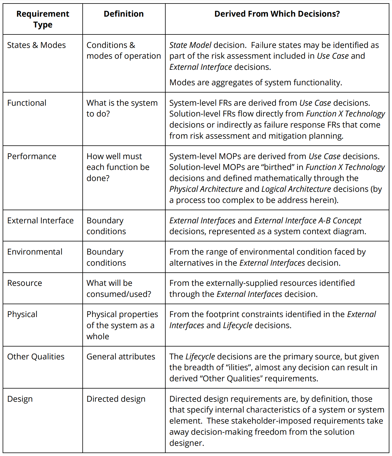
Table 2: Requirements Derivation by Type
The content of this article lays down the conceptual foundation for using a decision pattern (in general) and the solution design kernel (in particular) as the starting point for next-level requirements derivation. Readers are encouraged to look for the follow-on article that will provide a detailed example of these principles in action.
[1] Fitch, J.A. 2006. "Decision Driven Æ Design – Achieving Product and Process Breakthroughs." Workshop participant guide, delivered in multiple workshops during 2006.
[2] Mendonza, P. and Fitch, J.A. 2012. “Decision Management (DM) as the engine for scalable, crossdomain Systems Engineering”. Paper presented at 22nd Annual International Symposium of the International Council on Systems Engineering, Rome, Italy, 9-12 July.
[3] Fitch, J.A. 2016. “Product Scoping Decisions”, https://decisiondriven.wordpress.com/2016/08/30/product-scoping-decisions/, 30 August.
 John Fitch is a Principal Consultant and Course Presenter for Project Performance International. John brings over four decades of systems engineering, engineering management, consulting, and training experience to the PPI team. In 2012, John was certified by INCOSE as an Expert Systems Engineering Professional (ESEP). Within the field of systems engineering, John’s career has focused on decision management, requirements management, risk management, systems design &
architecture, product/technology road mapping, and innovation. In addition to defense/aerospace, John has guided initiatives in domains such as communications systems, software, energy, nanotechnology, medical devices, manufacturing systems, knowledge management, and business process improvement.
By John Fitch, for Project Performance International (PPI) [Fitch, John. “Rethinking Requirements Derivation: Part 2.” PPI Systems Engineering...
By John Fitch, for Project Performance International (PPI) [Fitch, John. “Extending the Lifecycle Modeling Language (LML) to Enable Decision...

Smart systems engineering is no longer just about building a model. In modern digital engineering environments, teams are expected to deliver...