
.svg) SPEC Innovations Team
SPEC Innovations Team
Rethinking Requirements Derivation: Part 1
By John Fitch, for Project Performance International (PPI) [Fitch, John. “Rethinking Requirements Derivation: Part 1.” PPI Systems Engineering...

By John Fitch, for Project Performance International (PPI) [Fitch, John. “Rethinking Requirements Derivation: Part 2.” PPI Systems Engineering Newsjournal (SyEN), no. 130, November 2023, pp. 18-32.]
This article continues the themes presented in Rethinking Requirements Derivation: Part 1, originally from PPI SyEN Edition #129. Part 1 introduced the theory and principles behind decision-centric requirements derivation. Novel ideas included:
Readers are encouraged to take a quick read through Part 1 to refresh their understanding
of these foundational ideas.
The goal of this article is to provide a working example of the theory/principles in practice.
The author of this article shares a name and common ancestry (traced to Puritans in Essex County, England in the early 1600s) with two notable inventors, aka systems engineering practitioners. The first John Fitch invented the steamboat in the 1780s, briefly ran this vessel in commercial service on the Hudson River, but failed to make a profitable business out of his invention. Sketches and mockups exist of this ungainly (by modern eyes) craft, but insufficient technical data was readily available from which to create a timely and thorough example of the design principles espoused herein.
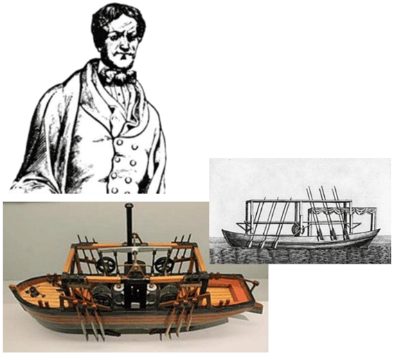
Figure 1: John Fitch and his steamboat
The second John Fitch, the great-great-grandson of the steamboat inventor, evidently had a “need for speed”. As a young man, he flew the P51 Mustang fighter during World War II. In the 1950’s he became a successful race car driver both in the United States and on the international racing circuits. [1] Racing for Mercedes Benz in 1955, he was paired with Pierre Levegh in the 24 Hours of Le Mans race. Ten minutes before John Fitch was to take the wheel from his partner, Levegh lost control and the car veered into a crowd of racing fans, bursting into flames and killing Levegh and over 80 spectators.
This event motivated John Fitch to develop automobile racing safety barriers and ultimately general-purpose automotive and highway safety inventions (15 patents in all) including the Fitch Inertial Barrier, our example system. On 20 September 1971, Fitch was awarded U.S. Patent #3,606,258 for Energy Absorbing Deceleration Barriers [2]. This innovation, a cluster of plastic barrels filled with varying amounts of sand that progressively slow and cushion a car in a crash, has been credited with saving over 17,000 lives since its initial deployment.
In the generalized language of an intellectual property claim, this invention is described as:
"Highway safety devices comprising an array of energy absorbing barrier units each preferably comprising a dispersible mass, effective, when struck by a vehicle, to bring the vehicle to rest at a rate of acceleration tolerable to the vehicle occupants without imposing and overturning or lifting moment on the vehicle."
The 13-page patent provides an excellent summary of the proposed system, both physically and functionally, from which it is relatively easy to reverse engineer the design decisions made by John Fitch in formulating his solution and to capture the solution as both physical and functional models within a modern MBSE environment.
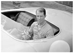
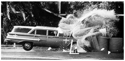
Figure 2: John Fitch and Fitch Inertial Barrier, aka Energy Absorbing Deceleration Barrier
To flesh out the problem definition and solution design for the Fitch Inertial Barrier, the author used Microsoft Excel tables for the initial capture of decisions, alternatives, functional models, and derived requirements. This raw data was imported into the Innoslate MBSE environment in which further model refinement and validation were performed, traceability relationships created, and visualizations produced to illustrate the principles of decision-centric requirements derivation.
Readers should refer to the article, Extending the Lifecycle Modeling Language (LML) to Enable Decision Patterns and Traceability, originally from PPI SyEN Edition #125, to understand how the LML and Innoslate metamodel/schema were extended to support new classes (e.g., Design Decision, Alternative) and associated attributes and relationships. The only additional metamodel extension required to populate the Fitch Inertial Barrier example was the reuse of LML’s “derives” relationship to build the last leg of the Decision -> chooses -> Alternative -> results in, aka “derives” -> Requirement traceability thread. LML had previously used the “results in” relationship for a different purpose, so the author decided that the definition of the existing LML “derives” relationship was closer to the intent of the Alternative -> results in -> Requirement construct.
Approximately a dozen hours of effort were required to:
Shortcuts were taken to save time, i.e., many entities were named only; full-text descriptions were written only to sufficient depth to clarify and validate the traceability relationships that are the focus of this article. Derived requirements were often grouped into placeholders that if fully elaborated might would yield 2-5 singularized requirements.
No “breakage” of the extended LML information metamodel was discovered during this process.
The reverse engineering effort reinforced the value of graphical representations of a system. The top plan view of two of the barrier “as-installed” configurations from the patent document (shown in Figure 3) was used to inform the use case, feature set, system context/external interface, and system design decisions. A picture was worth many model entities and even more words.
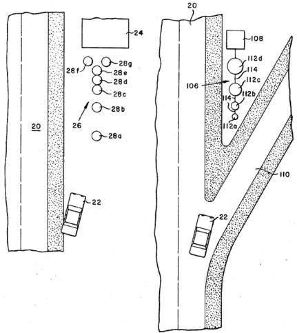
Figure 3: Top Plan Views of two Potential Barrier Configurations
Using the product/system design decision pattern presented in Part 1, it was a simple exercise to walk through the patent text and diagrams and map various aspects of the errant vehicle deceleration problem to either a decision (a question that demands an answer) or the proposed answer that represented a portion of the barrier solution concept.
Starting with the product scoping decisions that define the boundaries of the barrier system, yields Table 1.
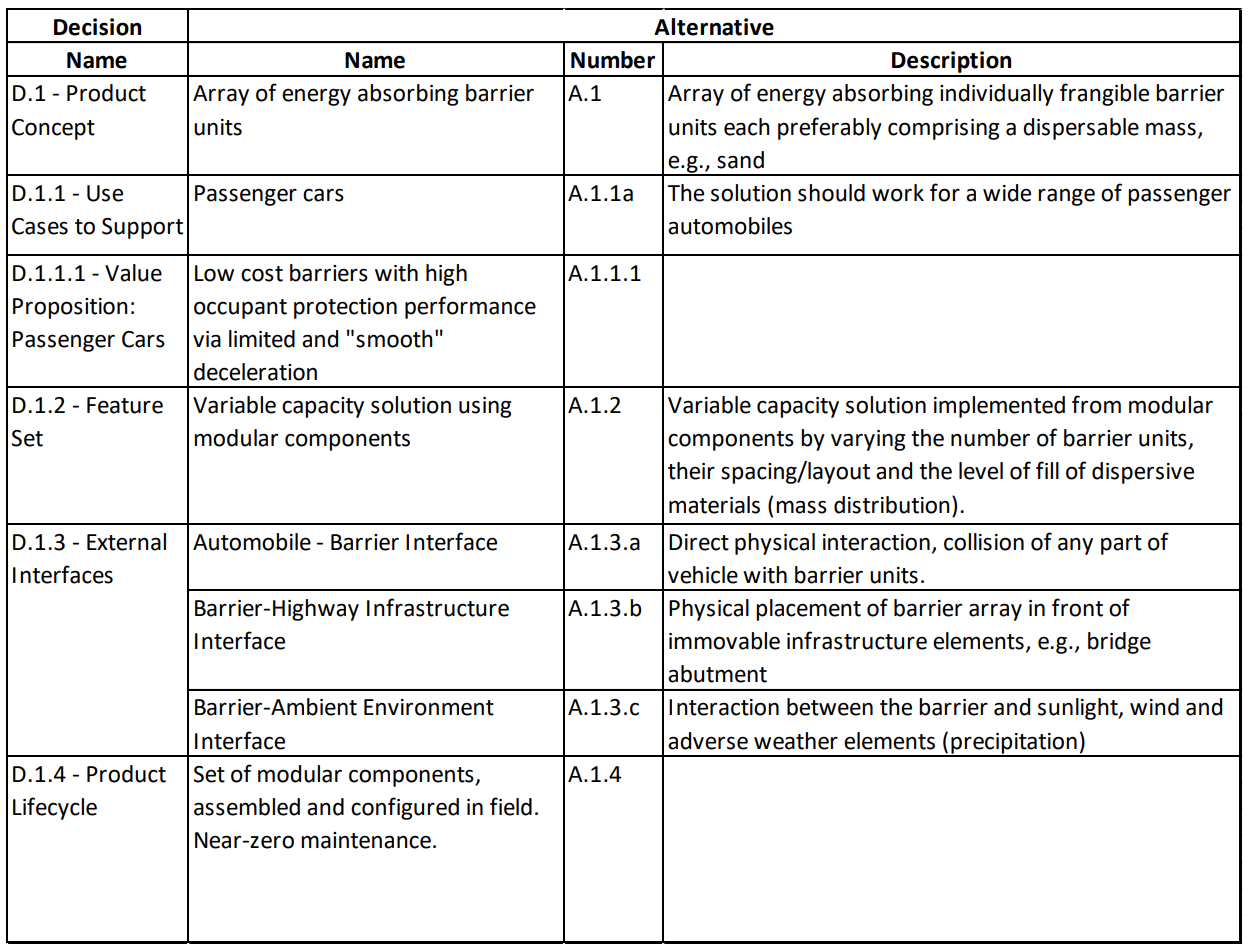
Table 1: Product Scoping Decisions for the Fitch Inertial Barrier
The product scoping decisions are the source of the functions (and associated performance) required of the barrier system. The use cases chosen and the system feature set demand operational functions and clarify how value will be delivered through these functions. External interface decisions define the inputs/outputs that must be received by/generated by the system and therefore clarify the functional transformations of inputs into outputs that must occur within the barrier system. Product lifecycle decisions create functional requirements for manufacturing, testing, deployment, support, and end-of-life.
The top-level lifecycle functions of the barrier system and their functional interactions may be visualized as a Functional N-Squared Diagram as shown in Figure 4.
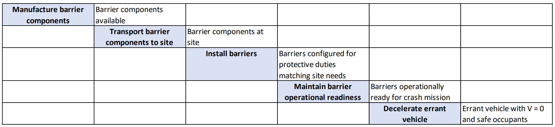
Figure 4: Lifecycle Functional N-Squared Diagram
As illustrated in Figure 5, after the product scoping decisions have been made, a pattern of six decisions may be used to recursively decompose the system design through successive levels of the solution physical architecture until non-developmental items are reached.
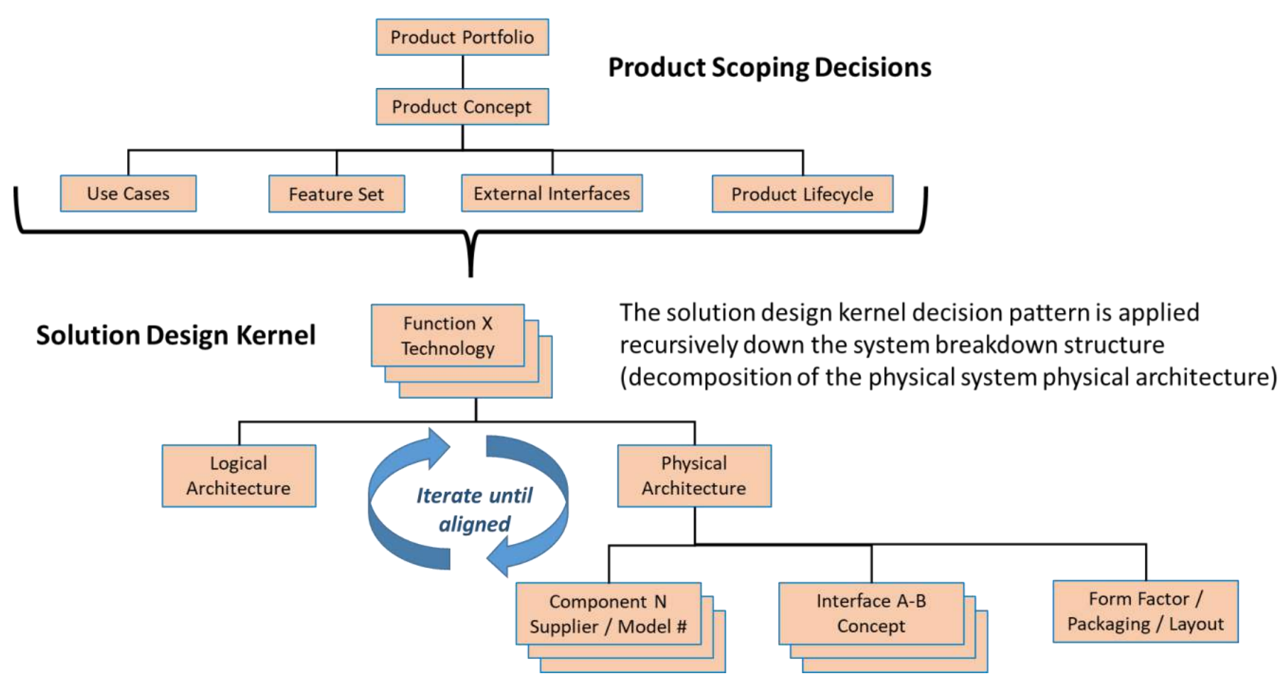
Figure 5: Product Scoping Decisions Set the Context for Recursive Use of the Solution Design Pattern Kernel
A decision must be made to determine how each system-level function will be delivered by the barrier system. In the case of a hardware system such as the energy-absorbing deceleration barriers, each of these decisions can be thought of as the choice of the technology (or method) to be used to deliver Function X.
Table 2 summarizes a set of lifecycle technology decisions implied in the Fitch Inertial Barrier patent. A subset of the lifecycle decisions are included for the deployment (e.g., installation) and support (e.g., maintenance) phases of the lifecycle; operational functions are represented by a decomposition of the Decelerate errant vehicle function – the essential purpose of the barrier system.
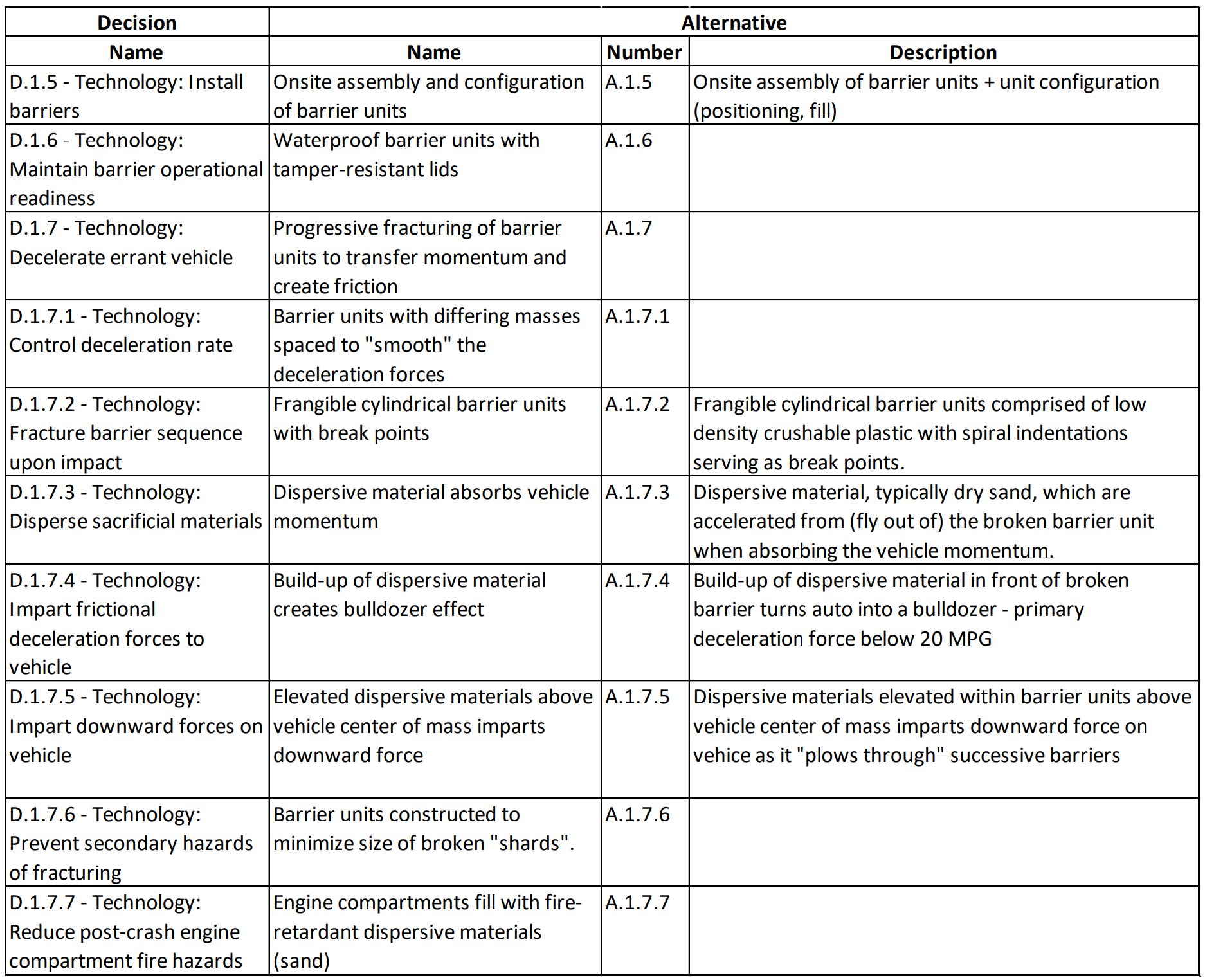
Table 2: Technology Decisions for the Fitch Inertial Barrier Functions
(How will system lifecycle functions be delivered?)
The barrier’s operational (Deceleration) functions may also be represented by a Functional N-Squared Diagram as shown in Figure 6.
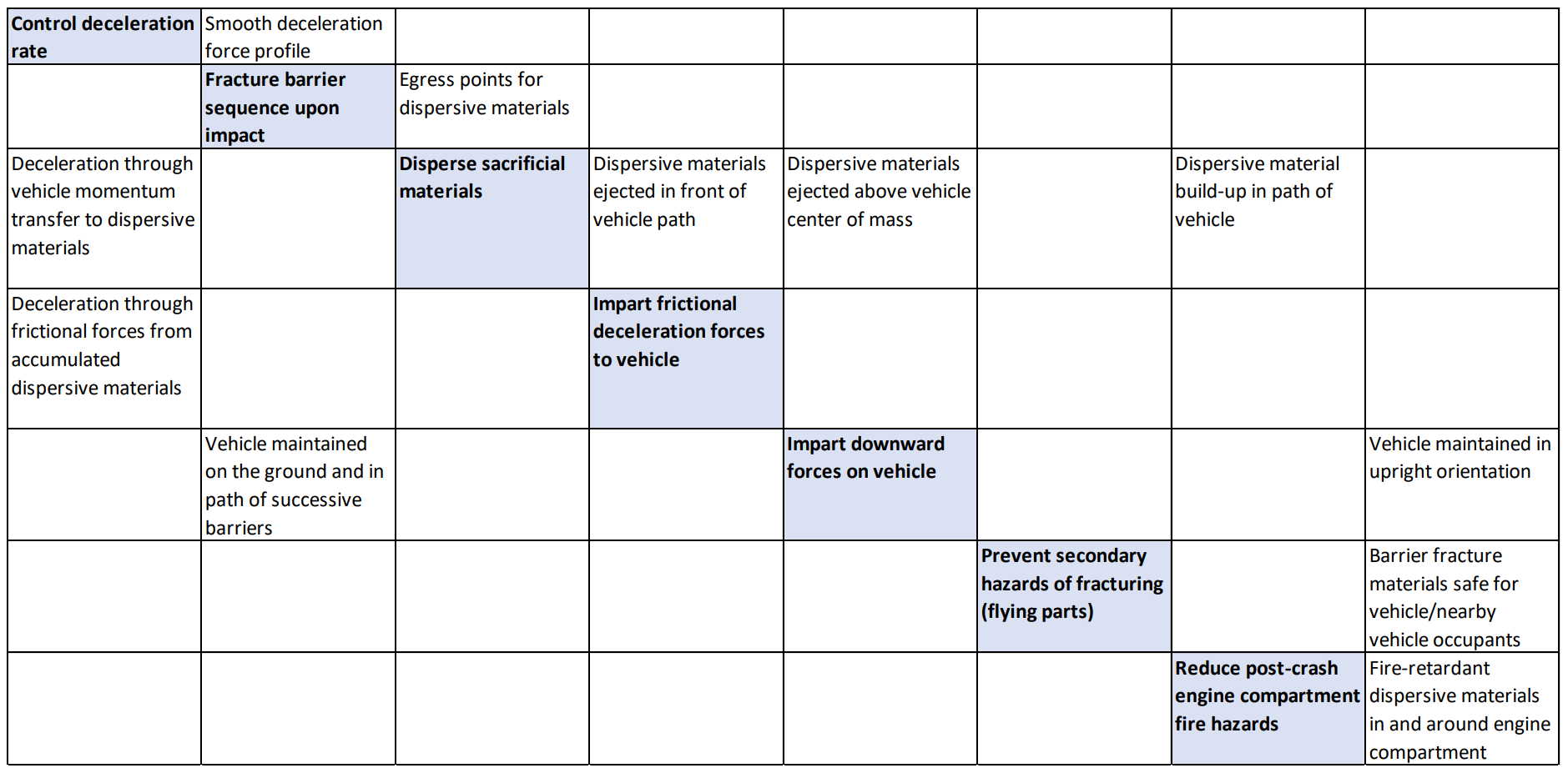
Figure 6: Functional N-Squared Diagram for Decelerate Errant Vehicle
If the explicit visualization of control flow logic is needed to make functional dependencies or timing clear, a combined control flow/item flow diagram may be used as shown in Figure 7. This Action Diagram has been generated using the Innoslate MBSE tool where barrier system functions are shown in grey rectangles and item flow between the functions are shown as green trapezoids.
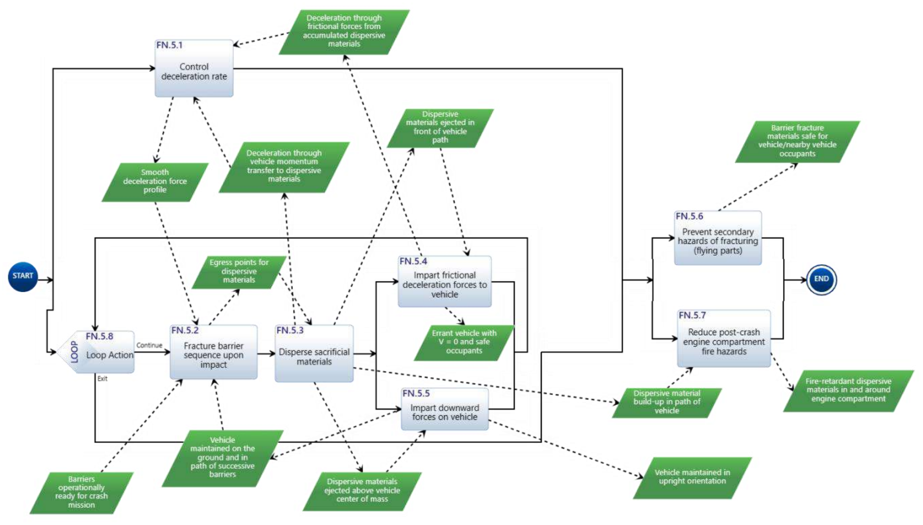
Figure 7: Innoslate Action Diagram for Decelerate Errant Vehicle
Readers should note the value of the Loop construct that shows the successive fracturing of barrier units and resulting forces on the vehicle, repeated until the vehicle velocity drops to zero or the last barrier is crushed. The number of loops required to accomplish the system deceleration function corresponds to the number of barrier units that are struck and fractured; this number will vary depending on vehicle mass and initial velocity for any barrier configuration.
The Action Diagram also includes an unexpected emergent property. The barrier system as originally conceived depends on the transfer of momentum from the vehicle to sacrificial/dispersive materials (e.g., sand) to deliver the deceleration function, i.e., from the Disperse sacrificial materials function. During testing, it was discovered that most of the deceleration force imparted below 20 MPH was produced by a “bulldozer” effect in which the friction associated with the vehicle pushing an ever-growing mountain of sand was more significant than the momentum transfer from the last barrier unit that was fractured. This is represented by the Impart frictional deceleration forces to vehicle function.
The functional and performance requirements derived from the decisions presented thus far must eventually be realized in physical entities, e.g., hardware components. Table 3 captures the physical architecture/design decisions for the Fitch Inertial Barrier system.
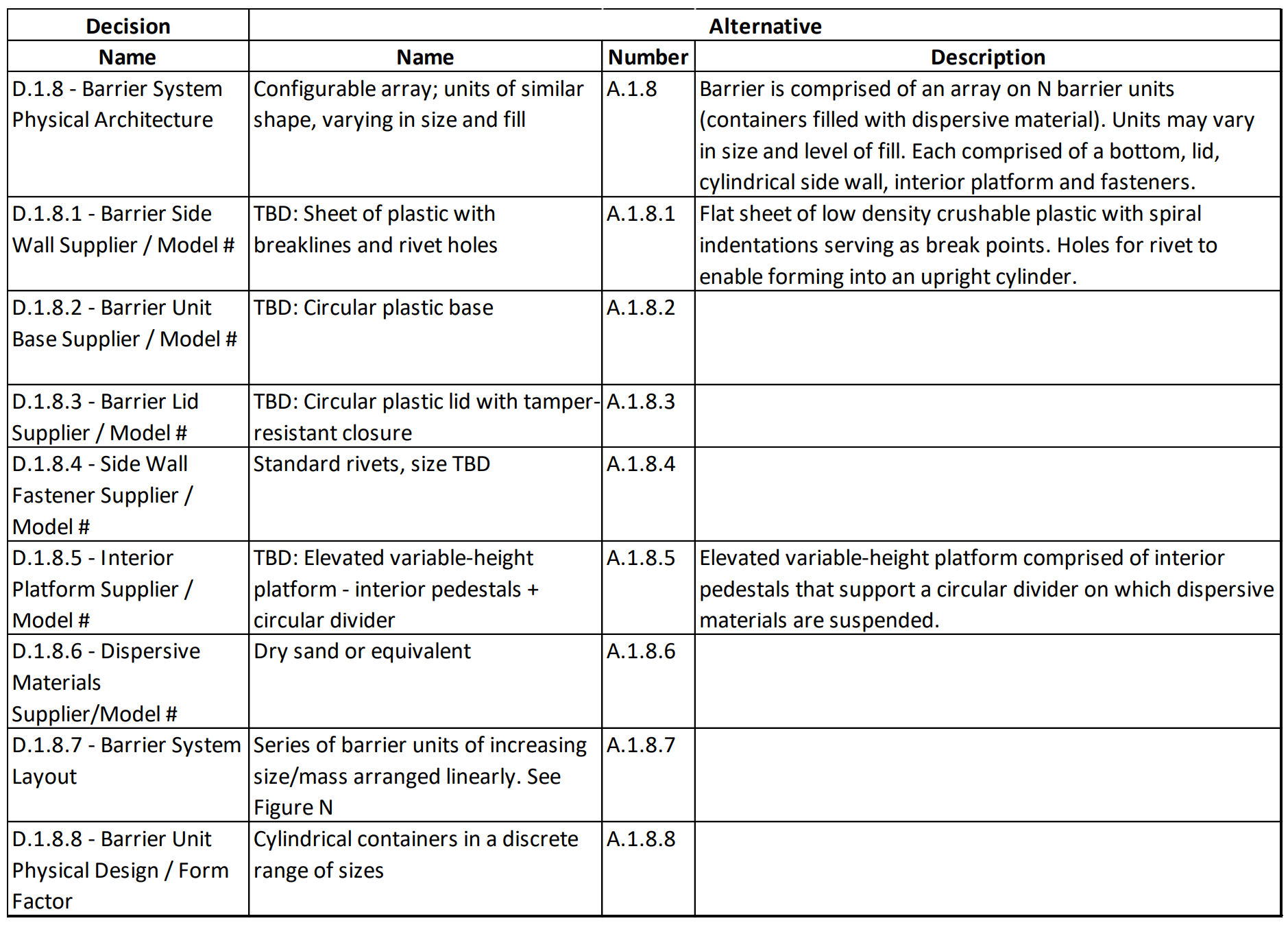
Table 3: Physical Architecture/Design Decisions for the Fitch Inertial Barrier Functions
The Physical Architecture decision gives birth to all system elements and the interfaces between them. As such, this decision is the point where the physical decomposition of the system into next-level elements occurs, and “existence” requirements are created that define the next-level structure of the solution.
Each system element must be either developed or procured as an off-the-shelf (OTS) component or non-developmental item (NDI). If the sourcing decision for a system element (Decisions D.1.8.1 through D.1.8.6 in Table 3) commits to the use of developmental items, these same characteristics must be captured in the developmental item’s specification. There will also be a decision as to how to implement each interface between system elements; the patent documentation for the barrier system lacked this detail so the analysis performed for this article simply captured a requirements placeholder for specifying each interface.
For the barrier system, there are two Form Factor / Packaging / Layout decisions shown in Table 3. The first represents the configuration of barrier units to form an array, as illustrated earlier in Figure 3. The second represents the physical structure and shape of each barrier unit, shown in Figures 8 and 9.
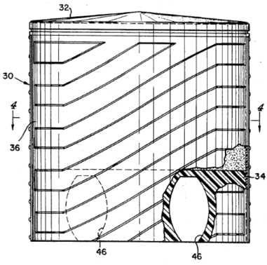
Figure 8: Barrier Unit Form Factor – Physical Layout #1
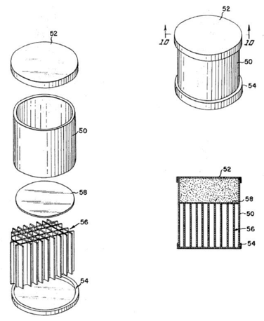
Figure 9: Barrier Unit Physical Design – Option #2
Each of the 25 decisions addressed thus far could be the source of one or more derived requirements based on the Structure, Behavior, Footprint, Interfaces, and Lifecycle (SBFIL) of the chosen alternative. The technology and architecture decisions for the system are the source of derived requirements that are allocated to system elements.
Space does not permit a full discussion of the more than 60 derived requirements captured from these 25 decisions. Because many of these requirements are placeholders, e.g., Durability across relevant environment(s) or Sidewall crushability characteristics, there are perhaps 200 requirements needed to fully specify the Fitch Inertial Barrier system and its next-level system elements.
Tables 4, 5, 6, and 7 capture the full Decision -> Alternative -> Requirements trace based on analysis to date.
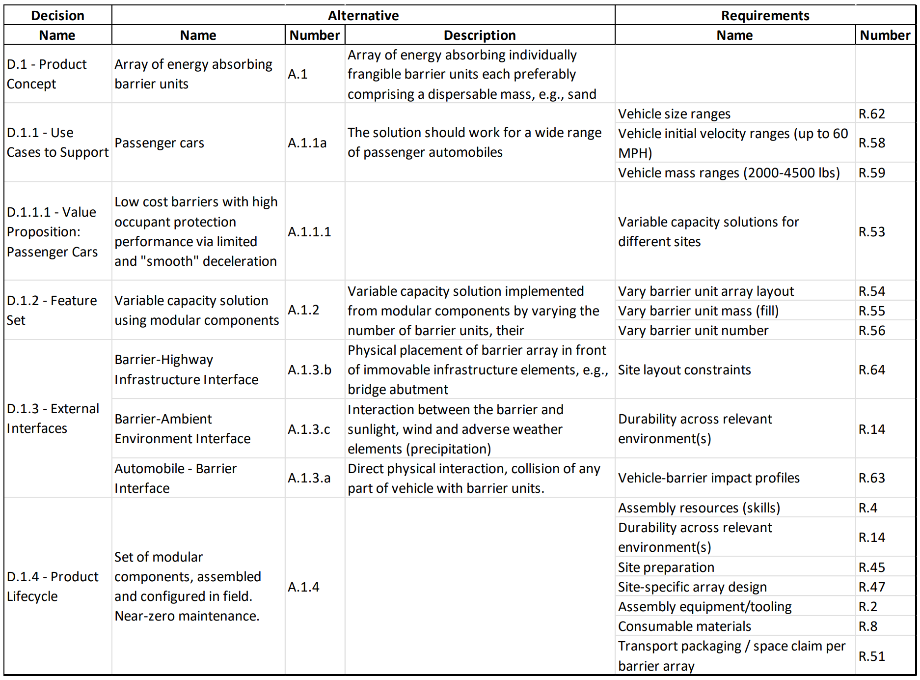
Table 4: Requirements Derived from Product Scoping Decisions
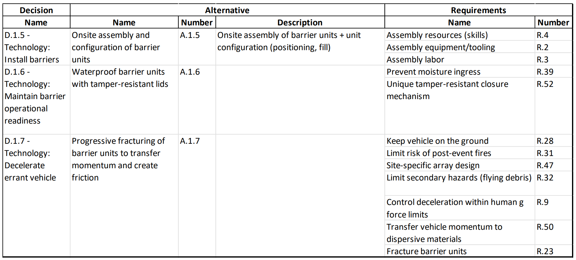
Table 5: Requirements Derived from Lifecycle Functional/Technology Decisions
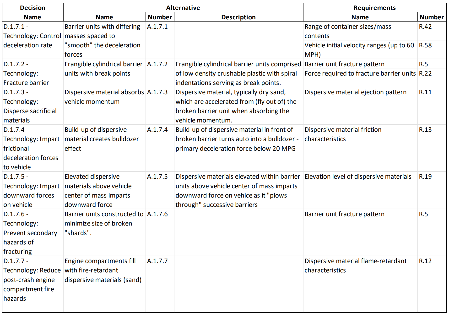
Table 6: Requirements Derived from Deceleration Functional/Technology Decisions
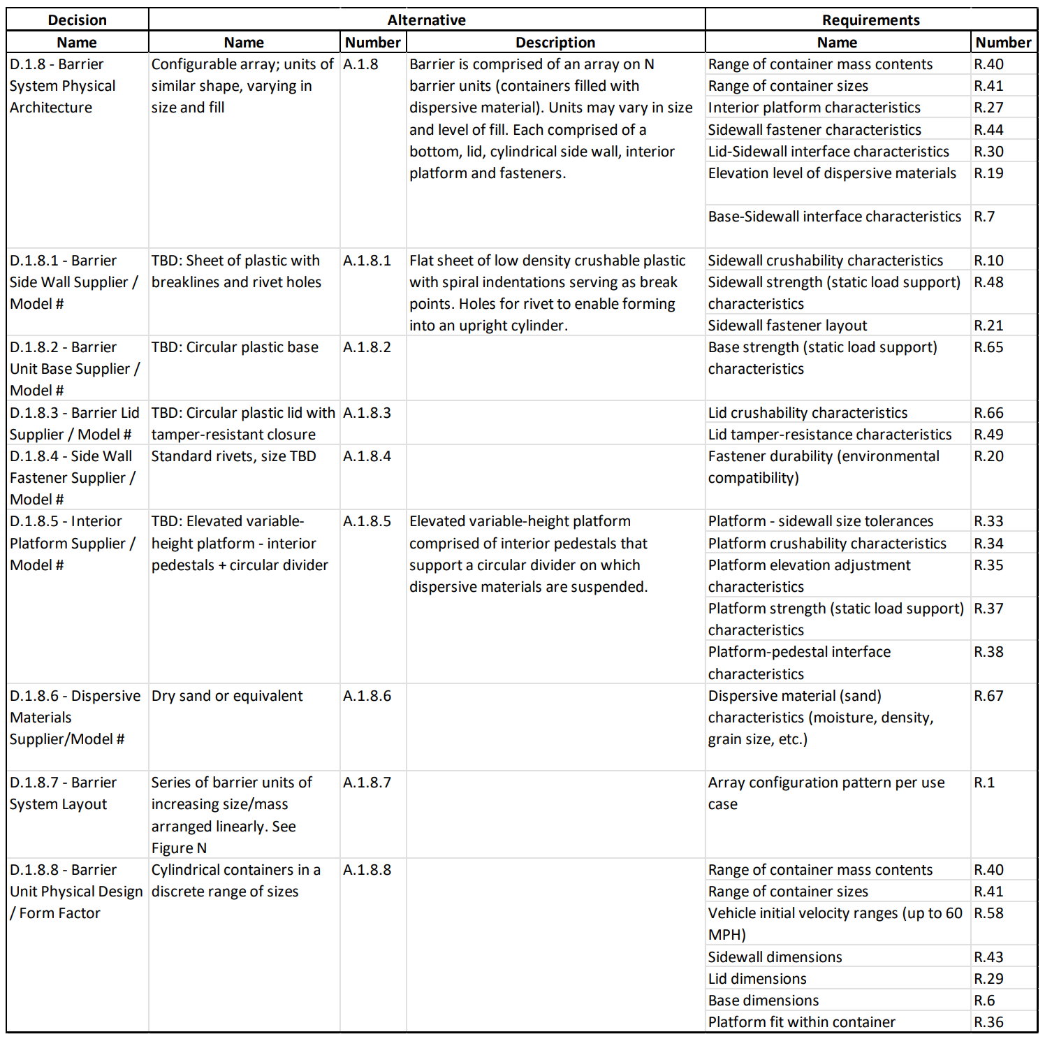
Table 7: Requirements Derived from Physical Architecture Decisions
Analysis of the example system presented in this article supports the assertion that the requirements for a system and the elements that comprise it can be comprehensively traced from “upstream” decisions. More than sixty requirements (many of them placeholders that would ultimately result in multiple requirement statements) have been identified as the inherent consequences that flow from the alternatives chosen in 25 decisions.
The elaboration of functional models and function-to-function interactions (control flow and item flow) was quite helpful in representing the next-level decomposition of a physical solution concept. This aided in maintaining alignment between the system's physical and logical architectures.
It was observed that a requirement may be derived and elaborated from multiple decisions, i.e. have multiple decision/alternative “parents.” For example, D.1.1.1 Value Proposition led to the requirement for Variable capacity solutions for different sites. This was elaborated and extended in D.1.2 Feature Set into requirements to:
D.1.7.1 Technology: Control deceleration rate further clarified the need for a Range of container sizes/mass contents. The implementation of this ability to vary container size and mass flowed down to D.1.8.5 – Interior Platform Supplier / Model # to specify the Platform elevation adjustment characteristics.
Initial “raw” requirements derived from decision alternatives did not lend themselves to immediate placement with a specification structure or numbering scheme. Often the decision-maker who identifies the derived requirement knows a great deal about the chosen alternative, but less about how to communicate its inherent consequences to a downstream solution provider. A second pass through the derived requirements will likely yield further refactoring and refinement of requirement statements to bring them up to “specification grade”.
Additional research is needed to evaluate and refine the SBFIL requirements derivation heuristic.
“How does the chosen alternative’s Structure, Behavior, Footprint, Interfaces, and Lifecycle (SBFIL) impose constraints on the rest of the system?”
While this question is universally valid and generally useful, it may be better to ask a different
derivation question for each type of decision within the system/product design pattern. For example, use case and lifecycle decisions are the primary source of system operational functions and associated performance requirements, so a question targeted at the system behavior that flows from each use case or lifecycle phase strategy may yield a more complete and precise definition of system functionality. Similar logic applies to technology decisions; each of which leads to functional and performance decomposition (also behavior). A system physical architecture decision is the primary source of next-level system structure and interfaces.
[1] Martin, Douglas, 2012. " John Fitch, Glamorous Racer With a Flair for Danger, Dies at 95". Article, New York Times, 31 October.
[2] Fitch, J.C. Energy Absorbing Deceleration Barriers. U.S. Patent #3,606,258. Filed 2 January 1969. Awarded 29 September 1971.
 John Fitch is a Principal Consultant and Course Presenter for Project Performance International. John brings over four decades of systems engineering, engineering management, consulting, and training experience to the PPI team. In 2012, John was certified by INCOSE as an Expert Systems Engineering Professional (ESEP). Within the field of systems engineering, John’s career has focused on decision management, requirements management, risk management, systems design &
architecture, product/technology road mapping, and innovation. In addition to defense/aerospace, John has guided initiatives in domains such as communications systems, software, energy, nanotechnology, medical devices, manufacturing systems, knowledge management, and business process improvement.
By John Fitch, for Project Performance International (PPI) [Fitch, John. “Rethinking Requirements Derivation: Part 1.” PPI Systems Engineering...

Establishing effective requirements is the foundation of successful project management and product development. Requirements Management provides a...

A single poorly written requirement can seem harmless during planning. In fact, many bad requirements go unnoticed at first because they appear...