

.svg) SPEC Innovations Team
SPEC Innovations Team
Dissecting SysML V2 Webinar
Don't feel like reading? Watch the recording!
.svg)
This article aims to provide a comprehensive overview of SysML for professionals new to MBSE to support successful MBSE adoption.
Systems Modeling Language (SysML) is a general-purpose, graphical modeling language used to specify, analyze, design, and document complex systems. It extends the Unified Modeling Language (UML) by incorporating additional concepts tailored for systems engineering.
SysML plays a vital role in Model-Based Systems Engineering (MBSE), an approach that emphasizes the use of models throughout the system development lifecycle. Unlike traditional document-based methods, MBSE relies on visual models to represent system requirements, behaviors, structures, and interactions.
SysML was developed by the SysML Partners, an industry consortium comprising aerospace, automotive, and defense organizations. The objective was to create a standardized modeling language that could effectively capture the multifaceted nature of systems engineering across various domains. Today, SysML is managed by the Object Management Group (OMG).
Blocks: SysML represents systems as "blocks," which can be either physical components (e.g., devices) or abstract entities (e.g., functions, requirements). Blocks have properties, operations, and relationships with other blocks.
Ports and Interfaces: SysML enables precise modeling of system interactions through ports and interfaces. Ports define interaction points, while interfaces specify the operations and signals exchanged between blocks.
Activities: SysML uses activities to model control and data flow within a system. These workflows, resembling flowcharts, help illustrate complex behaviors, processes, and algorithms.
Requirements Management: SysML allows engineers to capture and manage system requirements at multiple levels. Requirements can be traced to components, activities, and test cases, ensuring verification and validation throughout the development process.
Parametrics and Constraints: SysML supports parametric modeling, enabling the representation of mathematical equations, calculations, and constraints to analyze system behavior and performance.
Packages and Diagrams: SysML organizes models into packages, providing a modular structure for complex systems. Various diagrams help visualize different system aspects, making it easier to communicate and analyze designs.
SysML provides nine diagram types to represent different aspects of a system. These diagram types help modelers visualize and communicate various perspectives of a system's structure, behavior, and requirements.
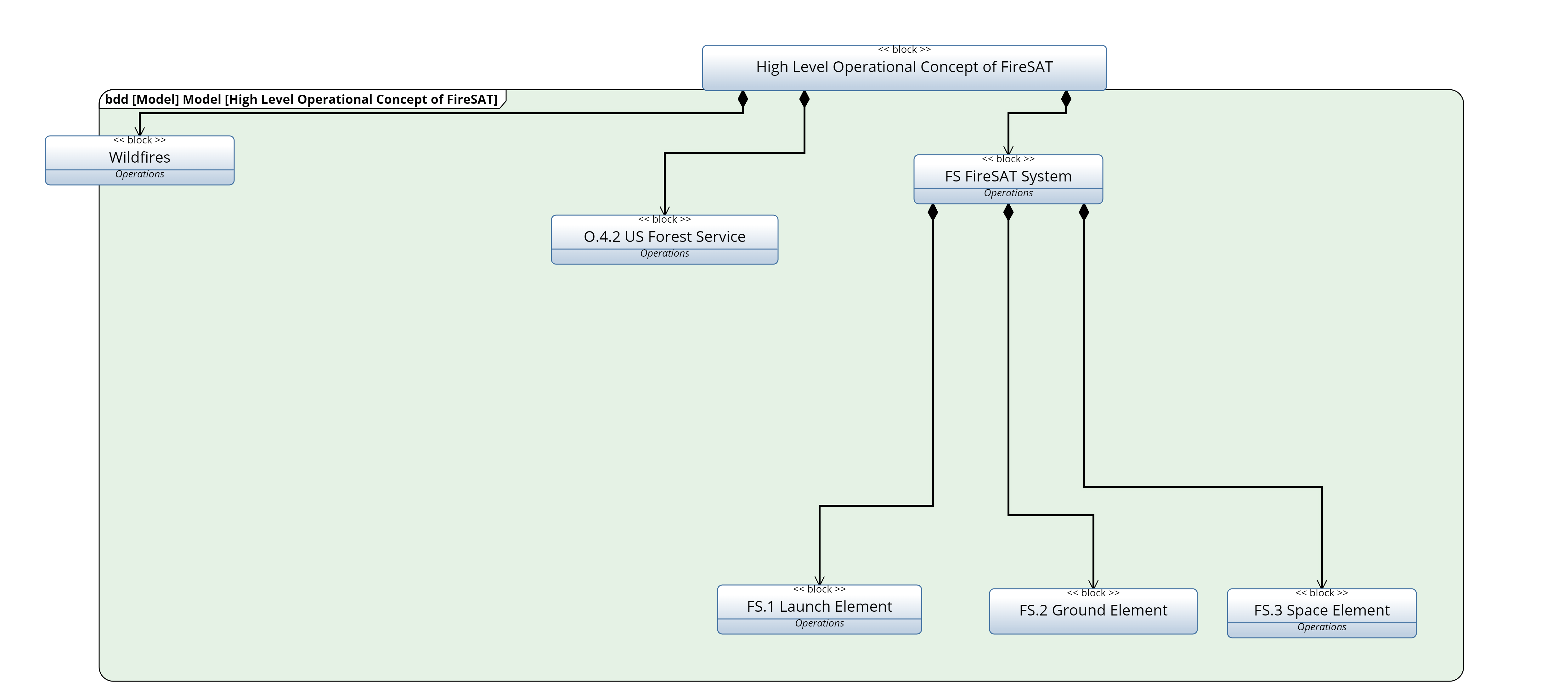
The Block Definition Diagram provides an overview of the system's structure by representing the system's blocks, their relationships, and properties. It illustrates the composition, containment, and hierarchy of blocks.
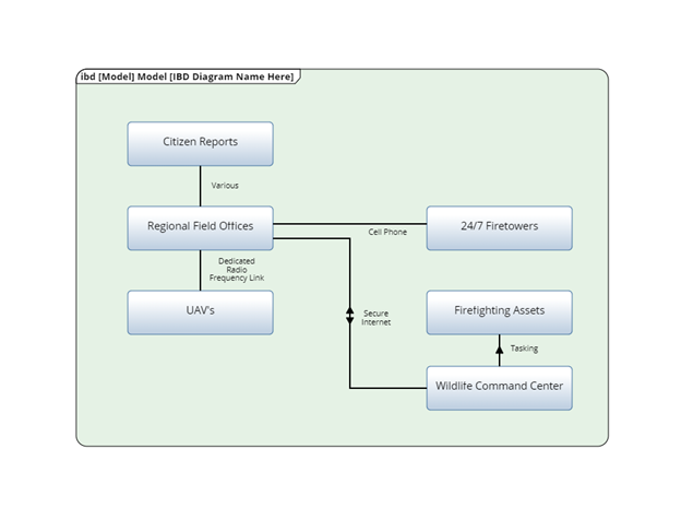
The Internal Block Diagram focuses on a block's internal structure. It shows a block's interconnected parts (called "internal blocks"), their ports, connectors, and relationships. It is used to depict the interactions and signal flow within a block's internal components.
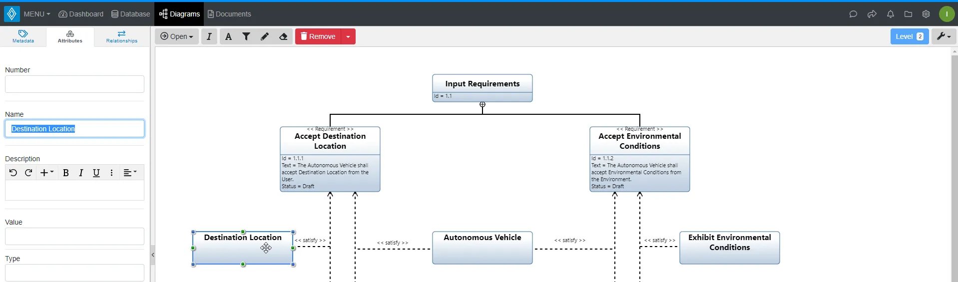
The Requirement Diagram captures the system requirements and their relationships. It allows the specification, organization, and traceability of requirements throughout the system development process.
The Use Case Diagram illustrates the interactions between the system and its external actors or users. It represents the system's functional behavior by depicting its different use cases (user interactions) and their relationships.

The Activity Diagram models the flow of control and data within the system. It represents the behavior and sequencing of activities, actions, and decisions in a system. It is useful for capturing complex processes, algorithms, and workflows.
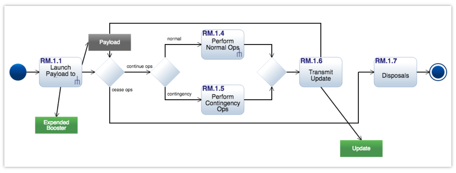
Note: You can use Innoslate to simulate cost, schedule, resources, and asset allocation from an activity diagram. Learn more about Innoslate's Monte-Carlo Simulator and Discrete Event Simulator.
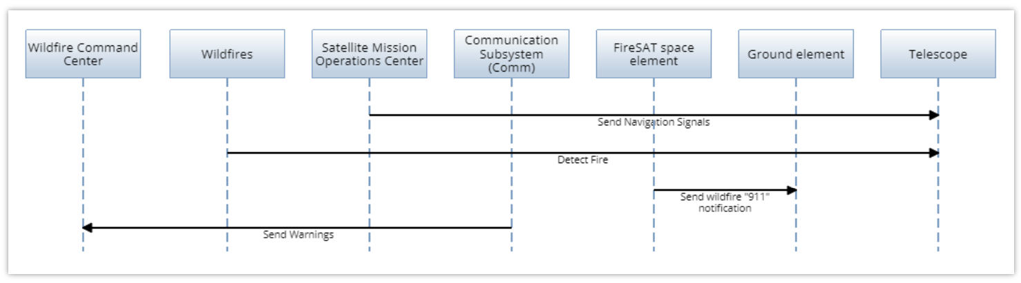
The Sequence Diagram shows the interaction between objects or blocks over time. It illustrates the chronological sequence of messages exchanged between the objects, helping to understand the system's dynamic behavior.
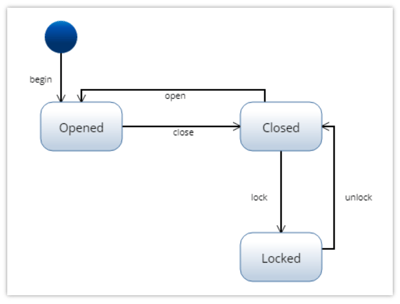
The State Machine Diagram represents the states, events, and transitions of a system or block. It captures the system's behavior by showing how it responds to events and changes its state over time.
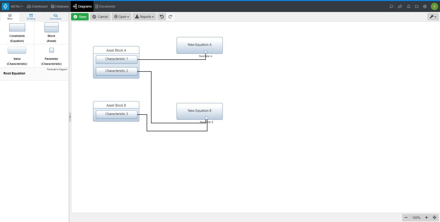
The Parametric Diagram depicts the parametric relationships, equations, and constraints within a system. It allows modeling mathematical expressions, calculations, and dependencies among system parameters.
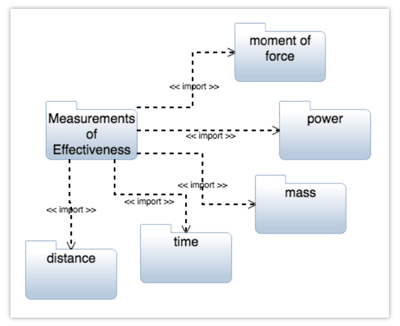
The Package Diagram provides an organizational view of the model by showing how the system's elements are grouped into packages. It helps manage the complexity of large models and facilitates modular design.
SysML is a powerful tool that enhances communication, analysis, and collaboration in systems engineering. It facilitates:
Requirements Analysis – Ensuring alignment between system needs and implementation.
Architecture Design – Structuring complex systems efficiently.
Verification & Validation – Maintaining traceability from requirements to testing.
Lifecycle Management – Supporting system development, deployment, and maintenance.
By adopting SysML, engineering teams can achieve greater clarity, consistency, and efficiency in developing complex systems, making it a cornerstone of modern MBSE practices.
Keep Learning:
.png)
Don't feel like reading? Watch the recording!

Model-Based Systems Engineering (MBSE) has revolutionized how engineers and organizations approach system design, development, and analysis. By...

In today's engineering landscape, Computer-Aided Design (CAD) is pivotal in system design, analysis, and optimization. At SPEC Innovations, we've...