
.svg) Steven Dam
Steven Dam
How MBSE and Requirements Management Work Together
Model-Based Systems Engineering (MBSE) and Requirements Management integrate to create a cohesive, traceable framework for complex system...
%20(200%20%C3%97%20100%20px)%20(800%20%C3%97%20400%20px)%20(7).png)
In systems engineering, many practitioners never create a behavior model. They work with requirements, develop plans, perform risk analyses, etc. When modeling, many professionals focus only on the physical models: block diagrams, interface diagrams, etc. Even when they are doing “functional analysis,” we frequently see hierarchy diagrams of the functions but no functional modeling beyond that. How do we know we have a complete set of tasks if we only create a hierarchical list?
At this point, behavior modeling becomes relevant. While exploring literature and online resources like the Systems Engineering Body of Knowledge (SEBoK), finding a comprehensive definition of behavioral modeling within systems engineering proves challenging. This article aims to provide MBSE newcomers with a thorough introduction to behavioral modeling.
A behavior model provides a way to show how different parts of the system interact with each other functionally to perform system tasks or functions. It’s used to determine the steps from an initial state to a final state of the system.
Behavioral models focus on the functional steps in between rather than various modes between states, as you would do with a State Transition Diagram. The sequencing of these steps also provides a way to see the impact of information on the path taken by the system. In addition, we can test the behavioral model by simulating the steps to determine if the process is feasible. We can better understand how the system will perform if we add time and other factors.
Several methodologies have been developed over the years to represent system behaviors:
Function Flow Block Diagrams (FFBDs): These diagrams depict the sequence of functions and their relationships, providing a clear visualization of functional flow within a system.
Integration DEFinition for Function Modeling (IDEF): A structured method for modeling activities and their interrelations, IDEF helps understand the process's decisions and actions.
Systems Modeling Language (SysML) Activity Models: SysML offers a standardized approach to modeling system behaviors, capturing the dynamic aspects of systems engineering.
Lifecycle Modeling Language (LML) Action Diagrams: LML provides a comprehensive framework for behavior modeling, with extensions that enhance its applicability in tools like Innoslate.
Among these, LML is noted for its nuanced approach to behavior modeling, particularly when utilized within platforms like Innoslate.
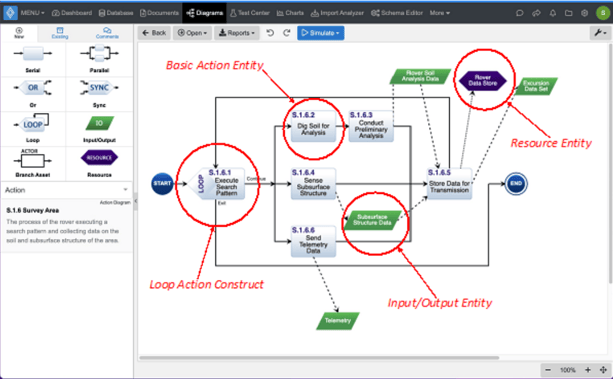
Innoslate Action Diagram
More Reading:
Innoslate is a modeling tool that supports various forms of behavior modeling, including the LML Action Diagram. The platform offers features such as decision points (e.g., LOOP, OR, SYNCH) and parallel constructs, enabling engineers to create detailed and accurate behavior models. These capabilities facilitate the simulation of system processes, assessing feasibility and performance under different conditions.
Explore Behavioral Diagrams:
Implementing behavior models in systems engineering offers several benefits:
Completeness: Ensures that all necessary functions are identified and addressed.
Visualization: Provides a clear representation of functional interactions within the system.
Simulation: Allows for testing and validation of processes before implementation.
Performance Analysis: Enables the evaluation of system behavior under various scenarios, aiding in optimization.
By incorporating behavior modeling into the engineering process, practitioners can enhance system design, reduce risks, and improve project outcomes.
More Beginner Readings:
Looking for a powerful tool to visualize and analyze your systems engineering data? Start making data-driven decisions with Innoslate. Sign up now!


Model-Based Systems Engineering (MBSE) and Requirements Management integrate to create a cohesive, traceable framework for complex system...
Don't feel like reading? Watch the recording!
Starting your journey into Model-Based Systems Engineering (MBSE) can be daunting for you and your team. While engineers are well-versed in ...