.svg) Steven Dam
Steven Dam

When a complex system fails, identifying the root cause is not always straightforward. A single component failure may be responsible, or several independent events may have occurred together to produce an unwanted outcome.
Fault Tree Analysis (FTA) gives engineers a structured way to understand these failure pathways. By starting with an undesired event and working backward through its potential causes, fault tree analysis helps teams visualize how individual failures and combinations of failures can affect an entire system.
Used in systems engineering, reliability analysis, and system safety analysis, FTA can help engineers identify vulnerabilities, investigate potential causes of failure, and evaluate ways to reduce risk.
With a model-based systems engineering (MBSE) platform such as Innoslate, engineers can take the analysis a step further by connecting the fault tree to the broader system model.
What is fault tree analysis?
Fault tree analysis is a top-down, deductive analysis method used to identify the events and combinations of events that can lead to an undesired system outcome.
The analysis begins with a specific undesirable outcome known as the top event. Engineers then work downward to identify the failures, conditions, and combinations of events that could cause it.
NASA describes fault tree analysis as a deductive technique in which an undesired state of a system is specified, and the system is analyzed in the context of its environment and operation to identify credible ways that the undesired event can occur.
A fault tree diagram visually represents these relationships using events and logic gates. The result looks like an inverted tree: the system-level failure appears at the top, with its potential causes branching beneath it.
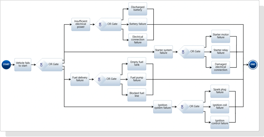
The Action Diagram below shows another way to visualize the fault tree, moving from the failure on the left to the branches on the right.
FTA can be used qualitatively to understand failure pathways or quantitatively when engineers have appropriate probability data available.
How does fault tree analysis work?
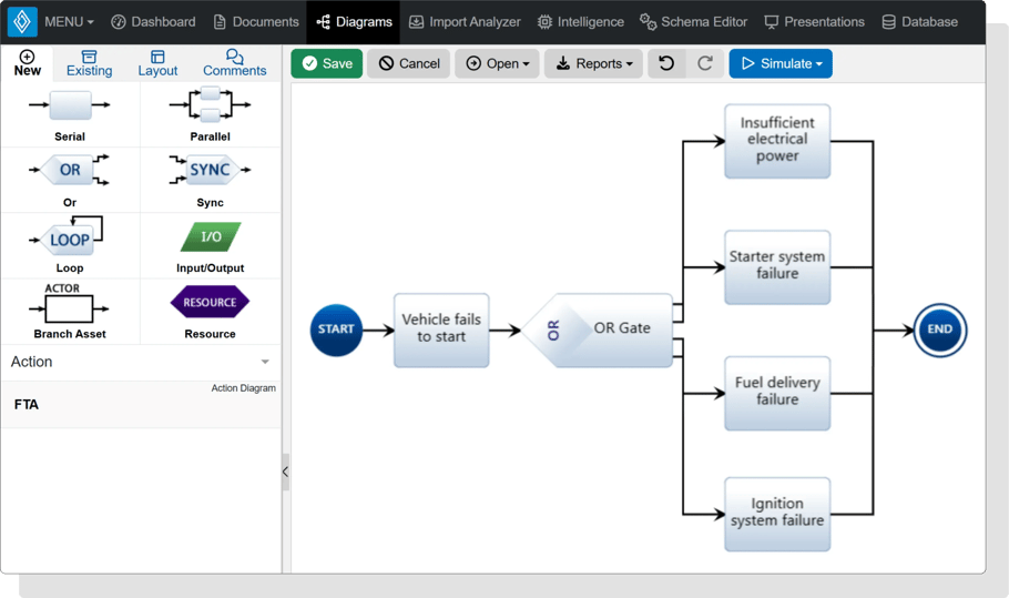
Fault tree analysis works backward from failure. Imagine an engineer is analyzing a vehicle and selects the following top event: Vehicle fails to start.
Rather than starting with every component that could potentially fail, FTA begins with that specific outcome and asks: What events could cause the vehicle to fail to start?
Possible causes might include:
-
Insufficient electrical power
-
Starter system failure
-
Fuel delivery failure
-
Ignition system failure
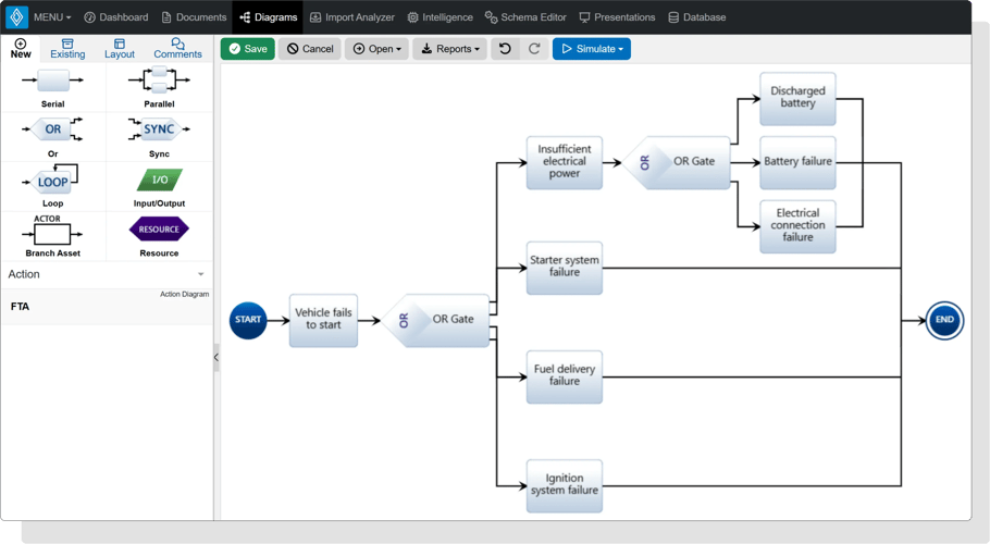
Each event can then be broken down further. For example, insufficient electrical power might result from a discharged battery, an internal battery failure, or a failed electrical connection.
The analysis continues until engineers reach basic events that do not require further decomposition for the purpose of the analysis.
This top-down structure makes it easier to see not only individual failures but also how different events can interact to create a system-level failure.
Key elements of a fault tree diagram
Understanding a few fundamental concepts makes a fault tree much easier to read.
Top event
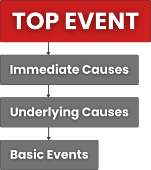
The top event is the undesirable outcome being analyzed. It establishes the scope and purpose of the fault tree.
A useful top event should be specific enough to analyze rather than something overly broad such as "system fails."
Examples might include:
-
Vehicle fails to start
-
Spacecraft loses electrical power
-
Communication with an unmanned system is lost
-
Safety system fails to activate
-
Component exceeds its allowable temperature
The remainder of the fault tree identifies the events that could produce this outcome.
Immediate causes
Immediate causes are events or conditions that directly contribute to the top event. They form the first level of branches beneath the top event and identify the primary failure paths engineers need to investigate.
For example, if the top event is Vehicle fails to start, immediate causes could include Insufficient electrical power, Starter system failure, Fuel delivery failure, and Ignition system failure.
Underlying causes
Underlying causes are the more specific events or conditions that contribute to an immediate cause. Engineers identify them by continuing to ask what could cause each event higher in the fault tree.
For example, Insufficient electrical power could be caused by a Discharged battery, Battery failure, or Electrical connection failure. These causes can be decomposed further as needed until the analysis reaches an appropriate level of detail.
Basic events
Basic events appear toward the bottom of the fault tree and represent failures or conditions that are not decomposed further.
These events form the building blocks of the failure pathways leading to the top event.
Fault tree logic gates
Fault tree logic gates describe how lower-level events must occur to produce a higher-level event.
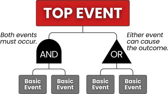
Two of the most important are AND and OR gates.
OR Gate
An OR gate means that any one of the input events can cause the event above it.
For example, suppose electrical power can be lost if:
-
The battery fails, OR
-
The generator fails, OR
-
A critical connection fails.
Any one of these events could be sufficient to produce the higher-level event.
AND gate
An AND gate means that all specified input events must occur for the event above them to happen.
Consider a system with redundant components. Loss of the capability might require:
-
Primary component fails, AND
-
Backup component fails.
If either component continues operating, the system retains the capability. The higher-level failure occurs only when both events happen.
These logical relationships are what make FTA more powerful than a simple list of possible failures.
Qualitative vs. quantitative fault tree analysis
Fault Tree Analysis can support both qualitative and quantitative analysis.
Qualitative fault tree analysis focuses on understanding the logical relationships between failures. It can help teams identify failure paths, single points of failure, critical combinations of events, and potential areas for mitigation.
Quantitative fault tree analysis incorporates probability data to estimate the likelihood of higher-level events or the top event.
For quantitative analysis to be meaningful, engineers need appropriate and reliable failure data. NASA notes that quantitative FTA depends on the quality and applicability of the underlying probability data.
Both approaches can support reliability analysis and system safety analysis. The appropriate method depends on the system, available data, and purpose of the analysis.
Fault tree analysis vs. FMEA: What's the difference?
Fault tree analysis and Failure Modes and Effects Analysis (FMEA) both help engineers investigate system failures, but they approach the problem from opposite directions.
FTA is top-down. It starts with an undesirable system-level event and asks: What could cause this to happen?
FMEA is bottom-up. It begins with individual failure modes and asks: What happens if this fails?
Consider the same vehicle example.
A FMEA might begin with a battery failure and analyze its potential effects on the vehicle. Engineers would identify the failure mode, effects, causes, and controls before evaluating its associated risk.
A fault tree might instead begin with "vehicle fails to start" and work backward to determine whether the battery, starter, fuel system, ignition system, or combinations of other events could cause the top event.
Neither approach has to replace the other. Using FTA and FMEA together can provide different perspectives on system risk: FMEA helps teams systematically investigate individual failure modes and their effects, while FTA helps reveal the logical pathways that can produce a specific undesirable outcome.

📖 Related Reading: How to Conduct a FMEA: Step-by-Step Guide + Example
How does FTA support system safety and reliability?
Fault tree analysis is widely applicable to systems in which understanding potential failures is important to safety, reliability, or mission success.
For systems engineers, FTA can help:
-
Identify potential causes of critical system failures
-
Reveal single points of failure
-
Understand combinations of failures that create hazards
-
Support reliability and system safety analysis
-
Evaluate architecture and design alternatives
-
Inform risk mitigation strategies
-
Develop or refine requirements
-
Communicate complex failure logic visually
-
Examine the potential effects of system changes
This becomes especially valuable for complex systems in aerospace, defense, automotive, and other engineering environments where components, functions, interfaces, and requirements are highly interconnected.
IBM also notes that FTA can be used alongside methods such as FMEA to identify causes of failure and support reliability and risk analysis.

How to perform fault tree analysis in Innoslate
Traditional fault trees can be developed as standalone diagrams. However, maintaining failure analysis separately from requirements, architecture, risks, and other engineering information can create another disconnected source of information.
Using fault tree analysis software within an MBSE environment provides an opportunity to connect the analysis to the broader system model.
Innoslate enables engineers to build and analyze fault trees while maintaining system information in a connected environment.
1. Identify the event you want to analyze
Begin by determining the undesired system event you want to investigate.
Clearly defining this top event gives the fault tree a specific objective and establishes the starting point for the analysis.
2. Build the fault tree diagram
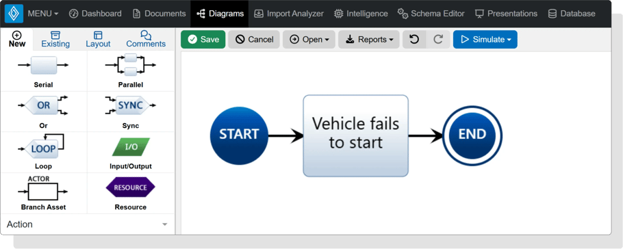
Use Innoslate's fault tree diagram to visually decompose the top event into its contributing causes.
Create an Action diagram and add a Serial entity for the top event.
3. Identify the immediate causes
Once the top event has been defined, identify the events that could directly cause it to occur. Choose the logical construct based on whether any one cause is sufficient or multiple causes must occur together.
Innoslate also supports AND logic through its Parallel construct. Both paths must execute and complete before the process can continue, making Parallel the closer match to a traditional fault tree AND gate. For example, a redundant system could lose a capability only when both the primary component and its backup fail.
Innoslate’s SYNC construct provides more general AND or non-exclusive OR behavior. Select the construct that reflects the logical relationship you want to model.
For the “Vehicle fails to start” example, use an OR gate to represent immediate causes that could each independently produce the top event.
At this stage, focus on the causes that could directly contribute to the top event. In the next step, you can break each of these events down further to identify its underlying causes.
4. Decompose the causes further
Once you've identified the immediate causes of the top event, keep breaking them down into more specific causes. For each event, ask: What could cause this to happen?
Continue this process for other branches of the tree until you reach a level of detail that is appropriate for your analysis.
4. Connect the analysis to the broader system model
One advantage of performing fault tree analysis in systems engineering within an MBSE platform is that the analysis does not have to exist as an isolated artifact.
Innoslate provides an integrated environment for requirements management, architecture and MBSE, risk management, modeling and simulation, verification and validation, and other lifecycle activities.
Connecting these activities can help teams evaluate failure information in the context of the system rather than maintaining separate documents that have to be manually reconciled.
💡 Learn how Innoslate connects fault tree analysis with the broader system model by exploring our Ultimate Guide to Model-Based Systems Engineering.
5. Use the results to inform engineering decisions
Once the failure pathways have been modeled, use the analysis to investigate vulnerabilities and potential mitigation strategies.
The findings may lead to changes in system architecture, additional redundancy, revised requirements, new controls, or further risk analysis.
📖 Related Reading: How to Perform Risk Management
Connect fault tree analysis to the bigger picture
Fault Tree Analysis provides a structured way to answer an important engineering question: What could cause this system-level failure?
By starting with a top event and working backward through contributing events, engineers can visualize failure pathways, understand logical relationships, identify critical combinations of failures, and evaluate opportunities to reduce risk.
But FTA becomes even more valuable when those insights are connected to the rest of the engineering lifecycle.
Instead of maintaining a fault tree as an isolated analysis, a model-based approach can help teams connect failure information with the requirements, architecture, risks, and other information that define the system.
Put FTA into practice in Innoslate.
Create a Free Forever Sandbox account and start building your system model.
